2 standby mode, 3 battery charging, Operation 3.2 standby mode – Magnum Energy ME-G Series User Manual
Page 40
Page 31
©
2015 Sensata Technologies
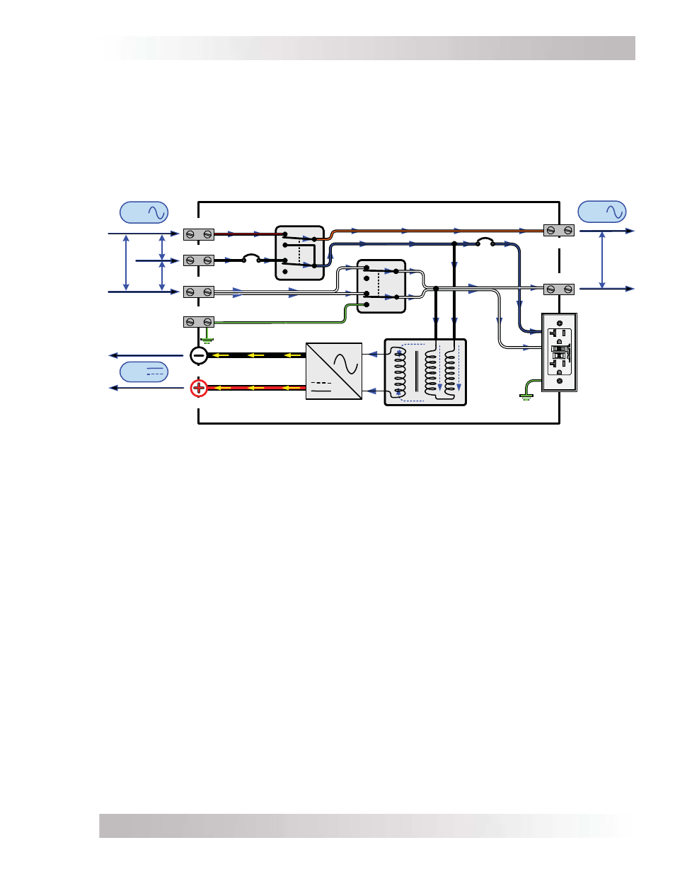
Operation
3.2 Standby
Mode
The ME-G Series features an automatic transfer relay and an internal battery charger when
operating in Standby mode. Standby mode begins whenever AC power (utility or generator) is
connected to the inverter’s AC input. Once the AC voltage and frequency of the incoming AC
power is within the AC input limits, the automatic AC transfer relay is activated. This transfer
relay passes the incoming AC power through the inverter to power the AC loads on the inverter’s
output. This incoming power is also used to activate a powerful internal battery charger to keep
the battery bank charged in case of a power failure. Refer to Figure 3-2 to see the fl ow of power
from the AC input to the DC and AC output while in Standby mode.
Figure 3-2, Power Flow – Standby Mode
3.3 Battery
Charging
The ME-G Series is equipped with a PFC (Power Factor Corrected) and PI (Proportional-Integral)
multi-stage battery charger. The PFC feature controls the amount of power used to charge the
batteries to obtain a power factor as close as possible to 1 (or unity). This causes the battery
charger to look like a resistor to the line (forces the charge current wave shape to mirror the voltage
wave shape). The PI feature allows the charger voltage and current to change independently.
These two features maximize the real power available from the AC power source (i.e., utility or
generator), which translates into less power wasted and increased charging capabilities.
When an AC source is connected to the AC input, the inverter begins monitoring for acceptable
AC voltage. Once the AC voltage is accepted, the AC transfer relay closes and the Charge mode
begins. After Charge mode begins, the inverter’s battery voltage is monitored to determine the
charging stage. If the battery voltage is low (≤12.8 VDC), the charger begins bulk charging. If the
DC voltage is high (>12.8 VDC), the charger will skip the Bulk and Absorb charge stages and go
directly to Float charging. However, if the incoming AC power is lost and returns within 2 minutes
the charge mode returns to the charge stage it was in prior to losing AC input—regardless of the
battery voltage.
The multi-stage charger in the ME-G Series can use up to fi ve different charging stages to help
monitor and keep the batteries healthy. The fi ve stages include an automatic 4-stage charging
process (Figure 3-3)—Bulk, Absorb, Float, and Full Charge—and a manual Equalization (EQ)
charge stage. The automatic 4-stage charge process provides complete recharging and monitoring
of the batteries without damage due to overcharging. The EQ stage (requires a remote control to
enable) can be used to stir up stratifi ed electrolyte and to reverse any battery plate sulfation that
may have occurred—if recommended by your battery’s manufacturer.
120
VAC
AC
OUT
Neutral-Ground
Transfer Relay
AC Hot
Transfer Relay
AC HOT 1 IN
AC HOT 2 IN
INPUT
(30A)
AC NEU IN
AC GROUND
Power Transformer
FET Bridge
AC
DC
DC
OUT
AC HOT 2 OUT
GFCI
(20A)
DC POSITIVE
DC NEGATIVE
AC NEU OUT
240
VAC
120
VAC
120
VAC
AC
IN
GFCI
120 VAC
OUTPUT