7 inverter notification requirements, 8 final inspection – Magnum Energy ME-G Series User Manual
Page 37
©
2015 Sensata Technologies
Page 28
Installation
2.6.4
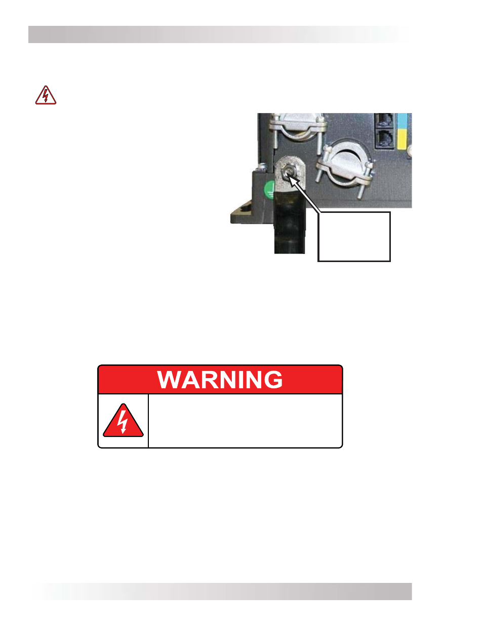
Connecting a Large DC Ground Wire
Marine installations require the DC ground wire to be the same size or one size smaller than the
negative cable. Use the following steps to allow a larger ground wire to be connected.
WARNING: Fire and Shock Hazard – disconnect all AC and DC sources before working
in the AC wiring compartment.
1. Remove the inverter’s AC access cover plate
(see Figure 1-3, Item 15).
2. Locate the DC Equipment Ground Terminal
(see Figure 1-2, Item 7).
3. Within the AC wiring area, locate the hex nut
on the backside of the DC ground terminal.
Use a 7/16” wrench/nut driver to remove the
hex nut, bolt, lock washer and DC ground
terminal.
4. Reverse the removed bolt, and place it back
in the chassis hole. Attach a correctly sized
ground cable with a ring terminal to the ME-G
chassis—as shown in Figure 2-15.
Note: Ring terminal must have a hole size ≥1/4”.
5. Place the washer and nut on the bolt—over
the ground cable—and securely tighten the
nut [from 4 to 5 lbf-ft (5.4 to 6.8 N-m)].
Replace the AC access cover plate.
Figure 2-15, Connecting a Large DC
Ground Wire
DC ground
terminal bolt/
nut, reversed
and tightened
2.7 Inverter
Notifi cation Requirements
A warning label as shown in Figure 2-16 is provided to inform all personnel that an inverter is
installed in your electrical system. Affi x this label in a clearly visible location at the electrical panel
that is being powered by the inverter. This is because it might be falsely assumed that the panel
is no longer “hot” after the AC power has been shut off, when power may actually still be available
due to the inverter automatically powering the panel.
This electrical system is equipped with an Automatic
Generator Starting (AGS) device and/or an inverter.
Disconnect all AC and DC power to the AGS and/or
inverter before performing any service to the electrical
system. Failure to do so can result in shock causing
serious injury or death.
PN: 62-0002 Rev A
Figure 2-16, Warning Label
2.8 Final
Inspection
1. Verify all cable runs are secured with wire ties or other non-conductive fasteners to prevent
chafi ng, or damage from movement and vibration.
2. Verify strain reliefs or grommets are in place to prevent damage to the wiring where it passes
through walls, bulkheads, or other openings.
3. Verify all AC connections are correct and torqued to a maximum of 16 lbf-in (1.8 N-m).
4. Replace the covers on the main electrical/distribution panel.
5. Replace the chassis access cover.
6. Verify the inverter’s front panel switch is in the OFF position.