Magnum Energy ME-G Series User Manual
Page 13
©
2015 Sensata Technologies
Page 4
Introduction
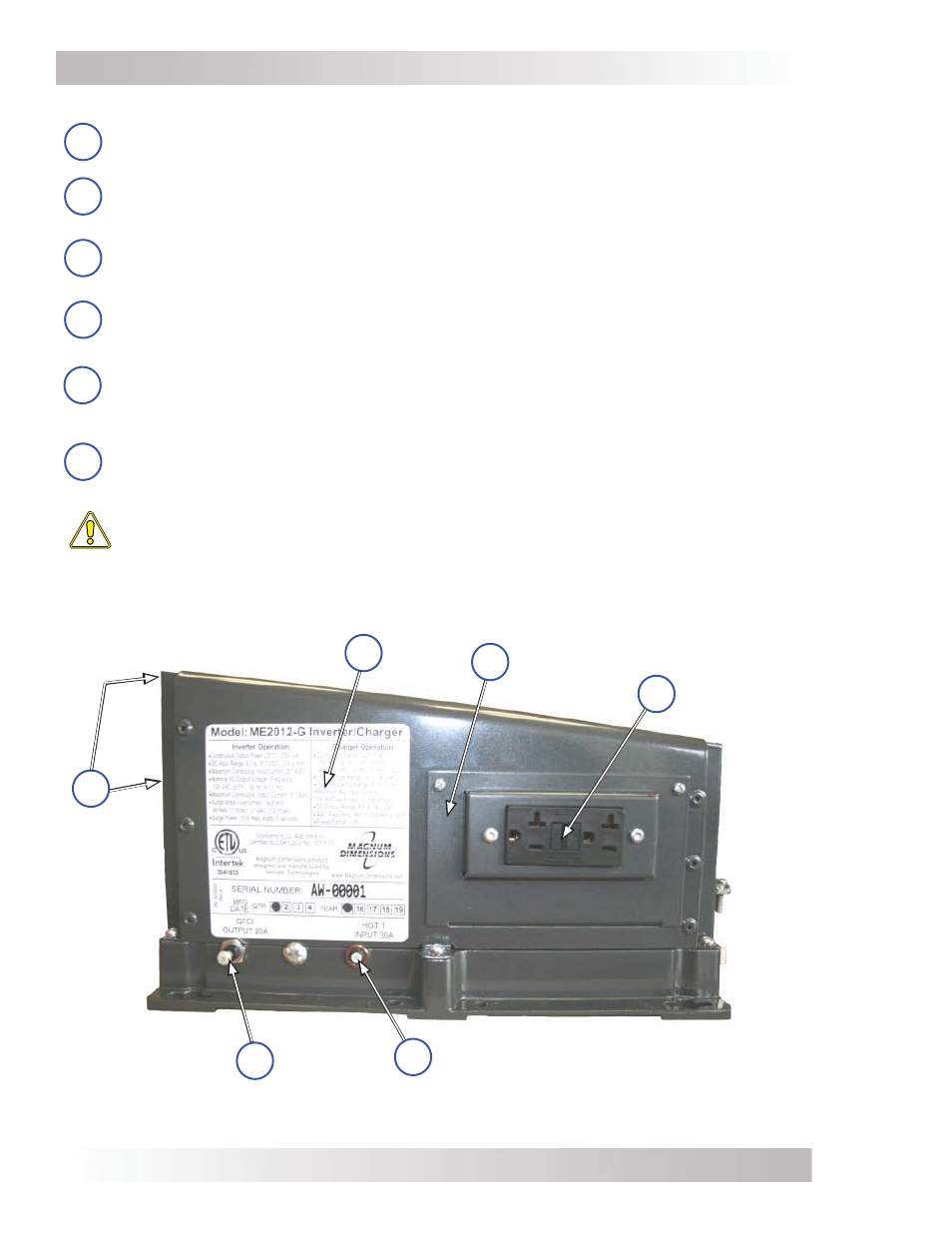
The left side of ME-G Series inverters are equipped with the following features (see Figure 1-3):
13
Exhaust Air Vents – ventilation openings that allow heated air to be removed by the
internal cooling fan.
14
Model/Serial Number Label – includes model/serial number information, date of
manufacture, and inverter and charger specifi cations. See the ME-G Series specifi cations
in Appendix A for more information and a list of available models.
15
AC Access Cover – provides access to the internal AC wiring terminal block (see Figure
2-8). This terminal block is used to hard wire all inverter AC input and output wiring
connections. Remove the two screws to access the AC wiring terminal block.
16
GFCI (Ground Fault Circuit Interrupter) – a 20-amp rated dual outlet that quickly
stops the flow of electricity in the event a ground fault occurs on the device that is
plugged into the inverter.
HOT 1 Input – this 30-amp circuit breaker protects the unit’s internal charger wiring
and pass-thru relay while in Standby mode. The circuit breaker pops out when it opens—
press in to reset. The input circuit breaker is not branch-rated, therefore branch-rated
circuit breakers must be installed in the inverter’s input wiring.
18
GFCI Output – this 20-amp circuit breaker is branch-rated and protects the wiring to the
GFCI outlet. This circuit breaker pops out when it opens—press in to reset. It can also be
manually pulled to disconnect the inverter’s loads.
CAUTION: The inverter’s internal AC transfer relay is rated for 30 amps per wired input
(not the GFCI circuit). The pass-thru current must be no greater than 30 amps per leg
or damage to the relays may occur.
17
Figure 1-3, Left Side Features
13
Exhaust Air
Vents
(back & right
side)
Model/Serial
Number Label
14
AC Access
Cover
GFCI Output
Circuit Breaker
HOT 1 Input Circuit
Breaker
17
15
18
16
GFCI