Magnum Energy ME-G Series User Manual
Page 12
Page 3
©
2015 Sensata Technologies
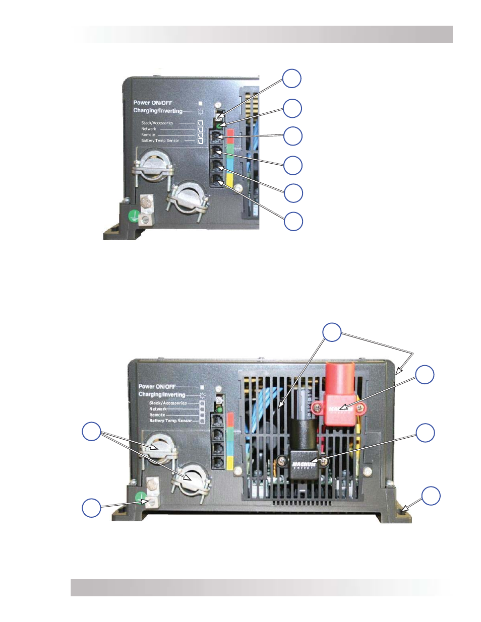
Introduction
Figure 1-2, Electrical Connection Points
Intake Air Vents
(and on right front side)
AC Entry/Exit
Connections
DC Equipment
Ground Terminal
Positive (+)
DC terminal
(under cover)
Negative (–)
DC terminal
(under cover)
11
10
7
8
Mounting
Flange
9
12
Figure 1-1, Power Switch, Status LED, and Accessory Connection Ports
Power ON/OFF Switch
Status LED Indicator
(Charging/Inverting)
Stack/Accessories Port
(red label – RJ11 connection)
Network Port
(green label – RJ11 connection)
Remote Port
(blue label – RJ11 connection)
Battery Temp Sensor Port
(yellow label – RJ11 connection)
6
4
3
2
1
5