3wiring and connection, 2 system configuration diagram 3-13 – Yaskawa Sigma-5 User Manual: Setup for Linear Motors User Manual
Page 97
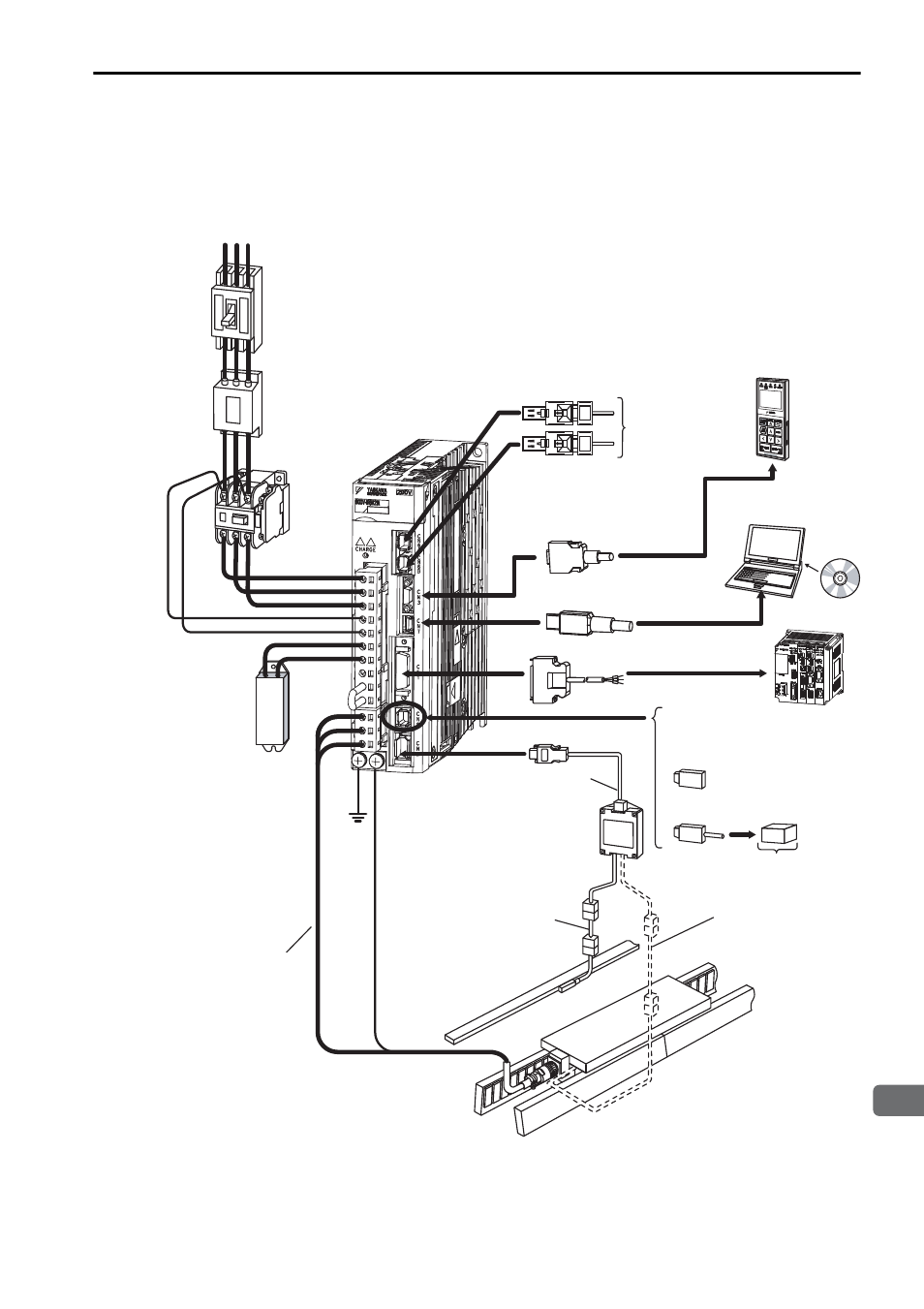
3.2 System Configuration Diagram
3-13
3
Wiring and Connection
(2) SGDV-A25
Using a Three-phase, 200-V Power Supply
∗1. Before connecting an external regenerative resistor to the SERVOPACK, refer to 3.4 Con-
necting Regenerative Resistors.
∗2. The connected device and cable depend on the model of the linear scale.
R S T
Noise filter
Molded-case
circuit breaker
(MCCB)
Magnetic contactor
I/O signal cable
SGDV-
A25
SERVOPACK
Power supply
Single-phase 200 VAC
Protcts the power supply
line by shutting the
circuit OFF when
overcurrent is detected.
Used to eliminate
external noise from
the power line.
Turns the servo
ON and OFF.
Install a surge
absorber.
Personal
computer
Connection cable
for personal computer
Digital
operator
When not using the safety
function, use the SERVOPACK
with the safety function jumper
connector (JZSP-CVH05-E,
provided as an accessory)
inserted.
When using the safety function,
insert a connection cable
specifically for the safety function.
Safety function
devices
Connection cable
for digital operator
Host controller
Regenerative
resistor*
1
Connect to the
MECHATROLINK-III
Linear servomotor
main circuit cable
Serial converter unit
*
2
Cable for connecting a
serial converter unit
*
2
Linear servomotor
with core
Linear scale
(Not included)
Cable for connecting a
hall sensor
Cable for connecting a
linear scale
*
2