Programming 5 - 4 – Yaskawa E7B Drive Bypass User Manual
Page 98
Programming 5 - 4
Definitions:
L = LonWorks Option Card
* = The Drive factory default
S = Speed Potentiometer
# = The H/O/A switch must be in the AUTO position
J = Native Protocols (N2 or P1)
to allow serial com. to control the Drive.
P = Pneumatic Pressure Transducer (3-15 PSIG)
@ = Jumpers required from S5 to S6 and S4 to SN
Parameter Reference:
b1-01: Speed Command Input Source
H3-13: Master Frequency Reference Terminal Selection
0: Operator
0: Main Fref TA1
1: Terminals
1: Main Fref TA2
H1-02: Terminal S4 Function Selection
d1-01: Frequency Reference 1
3: Multi-step Ref 1
d1-02: Frequency Reference 2
14: Fault Reset
d1-04: Frequency Reference 4
H1-03: Terminal S5 Function Selection
3: Multi-step Ref 1
6C: Com/Inv Sel 2
H3-02: Terminal A1 Gain Setting
Note: Hand mode run/stop for Drive and Bypass is always via
H3-08: Terminal A2 Signal Level
the front control panel HAND/OFF/AUTO switch.
0: 0 - 10 VDC
2: 4 - 20 mA
H3-09: Terminal A2 Function Selection
0: Frequency Bias
2: Aux Reference
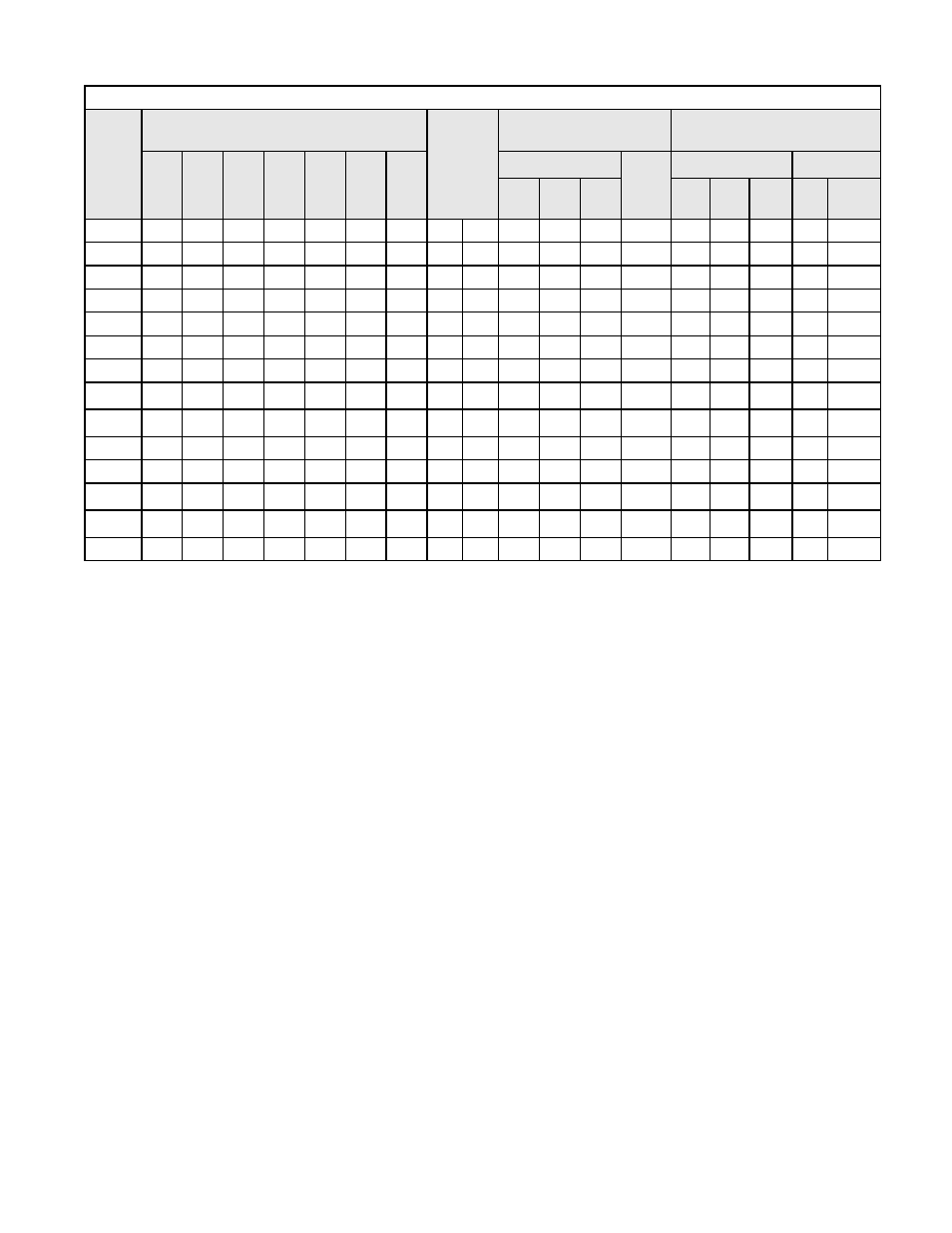
Table 5.2 Option Dependent Bypass Parameter Settings
Options
Parameters Effected by Options Specified and
Settings
Drive PCB
Switch S1
1 2
Resulting Hand Speed
Command Source
Resulting Auto Speed
Command Signal
b1-
01
H1-
02
H1-
03
H3-
02
H3-
08
H3-
09
H3-
13
Keypad
Speed
Pot.
Terminal A2
Serial Com
#
d1-
01
d1-
02
d1-
04
4-20
mA
0-10
VDC
3-15
PSIG
Run Speed
None
1*
14*
3*
0.0
2*
0
0*
Off* On*
X
X
None
1
14
3
0.0
0
0
0
Off
Off
X
X
P
1
14
3
0.0
2
0
0
Off
On
X
X
X
P and S
1
14
3
100*
2
2*
1
Off
On
X
X
X
S
1
14
3
100
2
2
1
Off
On
X
X
S
1
14
3
100
0
2
1
Off
Off
X
X
J
0
14
6C
0.0
2
2
0
Off
On
X
X
X
J
0
3
@
6C
0.0
0
2
0
Off
Off
X
X
X
J and P
0
3
@
6C
0.0
2
2
0
Off
On
X
X
X
X
J and S
1
14
6C
100
2
2
0
Off
On
X
X
X
L
0
14
6C
0.0
2
2
0
On
On
X
X
X
L
0
3
@
6C
0.0
0
2
0
On
Off
X
X
X
L and P
0
3
@
6C
0.0
2
2
0
On
On
X
X
X
X
L and S
1
14
6C
100
2
2
0
On
On
X
X
X