Bypass component descriptions, Bypass unit front control panel, Fig 1.4 e7 bypass unit appearance – Yaskawa E7B Drive Bypass User Manual
Page 23: Keypad operator, Indicating lights
Physical Installation 1 - 11
Bypass Component Descriptions
Bypass Unit Front Control Panel
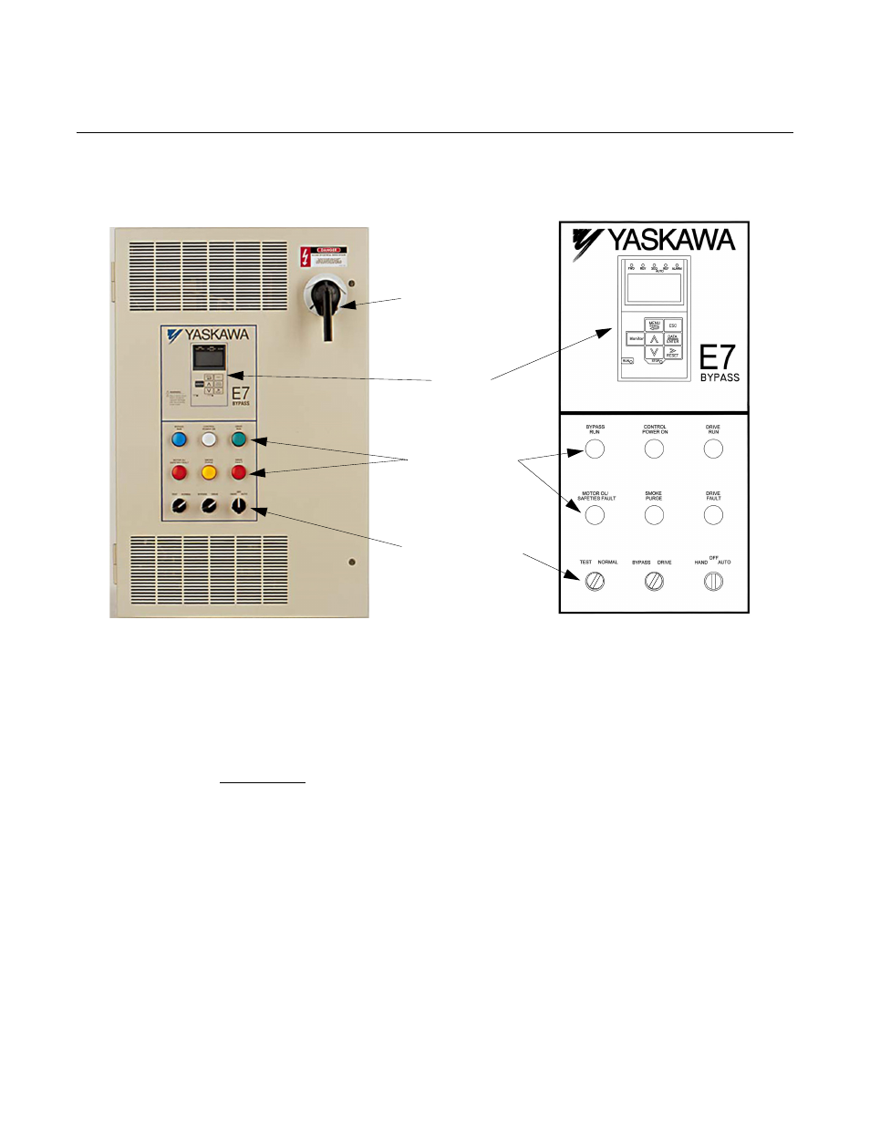
The external appearance, component names, and terminal arrangement of the Bypass unit is shown in Figures 1.4 through 1.8.
Fig 1.4 E7 Bypass Unit Appearance
Keypad Operator
In a Bypass unit the keypad operator is mounted flush with the hinged door of the enclosure. The addition of a HAND/
OFF/AUTO selector switch for the Bypass logic circuit makes the Hand, Off and Auto keys on the standard Drive keypad
operator redundant. In this Bypass configuration the keypad Hand, Off and Auto keys are disabled in the Drive firmware and a
mask (membrane) is placed over the keypad operator to cover these keys, avoiding the potential for confusion. The membrane
over the Drive keypad is non-removable on these Bypass units (In order to use the keypad copy function on a Bypass unit -
order a separate keypad, part number CDR001115).
Indicating Lights
On the enclosure door just below the digital operator are six 22 mm, 24 VAC LED indicating lights for: “Control Power”,
“Drive Run”, “Bypass Run”, “Motor OL/Safeties Fault “Drive Fault” and “Smoke Purge”. LED type indicating lights are pro-
vided to improve the reliability well beyond that of incandescent bulbs. LED’s have a MTBF of 100K hours, eliminating any
need for “push to test” type pilot lights.
Keypad
MCP
Disconnect
Indicating Lights
Selector Switches
Operator