Setting, Fig 5.14 drive display for pi control, auto mode, Programming 5 - 23 – Yaskawa E7B Drive Bypass User Manual
Page 117
Programming 5 - 23
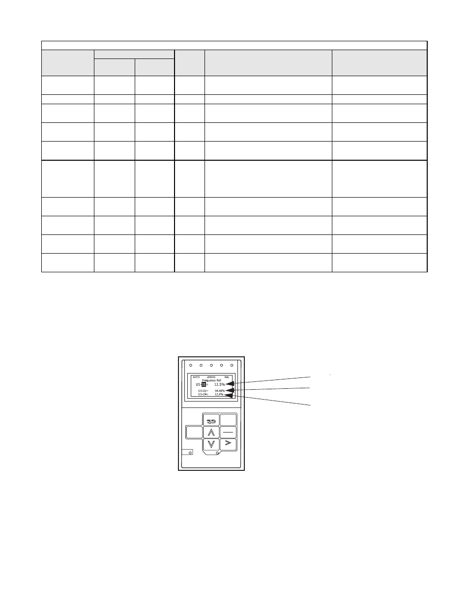
Digital Operator and Control Panel Display for PI Control
In Table 5.3, the o1-0X parameter listed setup the Drive display to indicate 3 variables for PI control as in Figure 5.14 when
the HAND/OFF/AUTO switch is in AUTO.
Fig 5.14 Drive Display for PI Control, AUTO Mode
Table 5.3 PI Control Parameter Settings in Bypass Units
PARAMETER
NUMBER
SETTING
UNITS
DESCRIPTION
KEYPAD DISPLAY
For Bypass Setting
Bypass & PI
Control
Bypass
Default
b1-01
SEE TABLE
5.4
SEE TABLE
5.2
N/A
Frequency Reference Selection – Selects the
speed command input source
Reference Source / Terminals
b5-01
1
0
N/A
PI Mode Selection – Enables PI mode
PI Mode Setting / PI Mode
H1-03
SEE TABLE
5.4
SEE TABLE
5.2
N/A
Terminal S5 Function Selection – Set for PI
Disable, turn off PI controller
Terminal S5 Sel / PI Disable
H1-04
SEE TABLE
5.4
4
N/A
Terminal S6 Function Selection – Set for
various operating modes
Terminal S6 Sel / Com/Inv Sel 2,
for example
H3-02
100
SEE TABLE
5.2
%
Terminal A1 Gain Setting
Terminal / (0-1000)
H3-08
SEE TABLE
5.4
SEE TABLE
5.2
N/A
Terminal A2 Signal Level – Signal selection,
0 to 10 VDC (Drive control board switch
S1-2 off) or 4 to 20 mA (Drive control board
switch S1-2 on)
Term A2 Signal / 0-10 VDC
H3-09
B
SEE TABLE
5.2
N/A
Terminal A2 Function Selection – Selects
how this input will be used by the Drive
Terminal A2 Sel / PI Feedback
o1-03
1
0
%
Digital Operator Display Selection – Set for
percent
Display Scaling / (0-39999)
o1-06
1
0
N/A
User Monitor Selection Mode – Enables a
custom display for PI Control monitoring
Monitor Mode Sel / 1: 3 Non
Selectable
o1-08
24
3
N/A
Third Line User Monitor Selection – Display
PI Feedback
3rd Monitor Sel / 24: PI Feed-
back
PI SETPOINT
FWD
REV
SEQ
REF ALARM
AUTO
- - - - - - - - - - - - - - - - - - - - - - - - - - - - -
OUTPUT
PI FEEDBACK
RUN
Monitor
DATA
ESC
MENU
ENTER
RESET
STOP