Termination configuration - power wiring – Yaskawa E7B Drive Bypass User Manual
Page 40
Electrical Installation 2 - 2
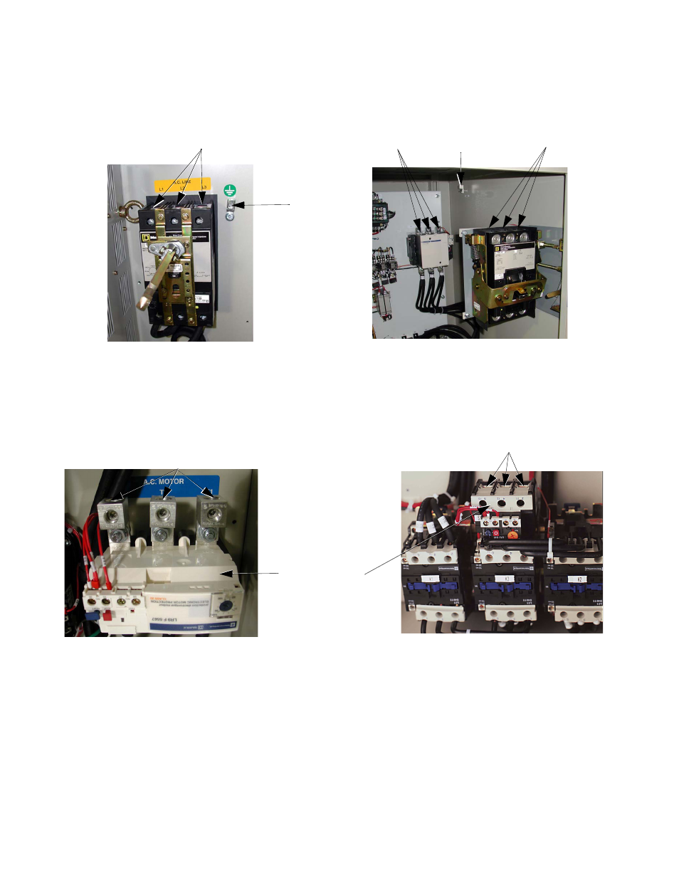
Termination Configuration - Power Wiring
The Circuit Breaker/MCP is located in the upper right hand side of the Bypass unit. The Bypass three phase input power
connection is made to the input terminals of the MCP. See Figure 2.1 and 2.2 for representative examples.
Fig 2.1 Typical Input Power Connection,
Fig. 2.2 Typical Input and Output Power
Wall Mount Unit
Connections, Floor Mount Unit
The OverLoad Relay (OLR) is mounted to the contactor assembly or back panel (depending on rating), just above the bypass
contactor. The Bypass three phase output power connection to the motor is made to the output terminals of the OverLoad
Relay. See Figure 2.3 for representative examples.
Fig 2.3 Typical Output Power Connection, Wall Mount Units
Overload Relay
Motor Connections
Input Power
Ground Lug
Ground Lug
Input Power
Motor
Connections
Motor Connections
- Tag Generator (30 pages)
- MP3300iec (82 pages)
- 1000 Hz High Frequency (18 pages)
- 1000 Series (7 pages)
- PS-A10LB (39 pages)
- iQpump Micro User Manual (300 pages)
- 1000 Series Drive Option - Digital Input (30 pages)
- 1000 Series Drive Option - CANopen (39 pages)
- 1000 Series Drive Option - Analog Monitor (27 pages)
- 1000 Series Drive Option - CANopen Technical Manual (37 pages)
- 1000 Series Drive Option - CC-Link (38 pages)
- 1000 Series Drive Option - CC-Link Technical Manual (36 pages)
- 1000 Series Drive Option - DeviceNet (37 pages)
- 1000 Series Drive Option - DeviceNet Technical Manual (81 pages)
- 1000 Series Drive Option - MECHATROLINK-II (32 pages)
- 1000 Series Drive Option - Digital Output (31 pages)
- 1000 Series Drive Option - MECHATROLINK-II Technical Manual (41 pages)
- 1000 Series Drive Option - Profibus-DP (35 pages)
- AC Drive 1000-Series Option PG-RT3 Motor (36 pages)
- Z1000U HVAC MATRIX Drive Quick Start (378 pages)
- 1000 Series Operator Mounting Kit NEMA Type 4X (20 pages)
- 1000 Series Drive Option - Profibus-DP Technical Manual (44 pages)
- CopyUnitManager (38 pages)
- 1000 Series Option - JVOP-182 Remote LED (58 pages)
- 1000 Series Option - PG-X3 Line Driver (31 pages)
- SI-EN3 Technical Manual (68 pages)
- JVOP-181 USB Copy Unit (2 pages)
- JVOP-181 (22 pages)
- SI-EN3 (54 pages)
- MECHATROLINK-III (35 pages)
- SI-ET3 (49 pages)
- EtherNet/IP (50 pages)
- SI-EM3 (51 pages)
- 1000-Series Option PG-E3 Motor Encoder Feedback (33 pages)
- 1000-Series Option SI-EP3 PROFINET (56 pages)
- PROFINET (62 pages)
- AC Drive 1000-Series Option PG-RT3 Motor (45 pages)
- SI-EP3 PROFINET Technical Manual (53 pages)
- A1000 Drive Option - BACnet MS/TP (48 pages)
- 120 Series I/O Modules (308 pages)
- A1000 12-Pulse (92 pages)
- A1000 Drive Software Technical Manual (16 pages)
- A1000 Quick Start (2 pages)
- JUNMA Series AC SERVOMOTOR (1 page)
- A1000 Option DI-101 120 Vac Digital Input Option (24 pages)