Fig 5.15 drive display for pi control, hand mode, Programming 5 - 24 – Yaskawa E7B Drive Bypass User Manual
Page 118
Programming 5 - 24
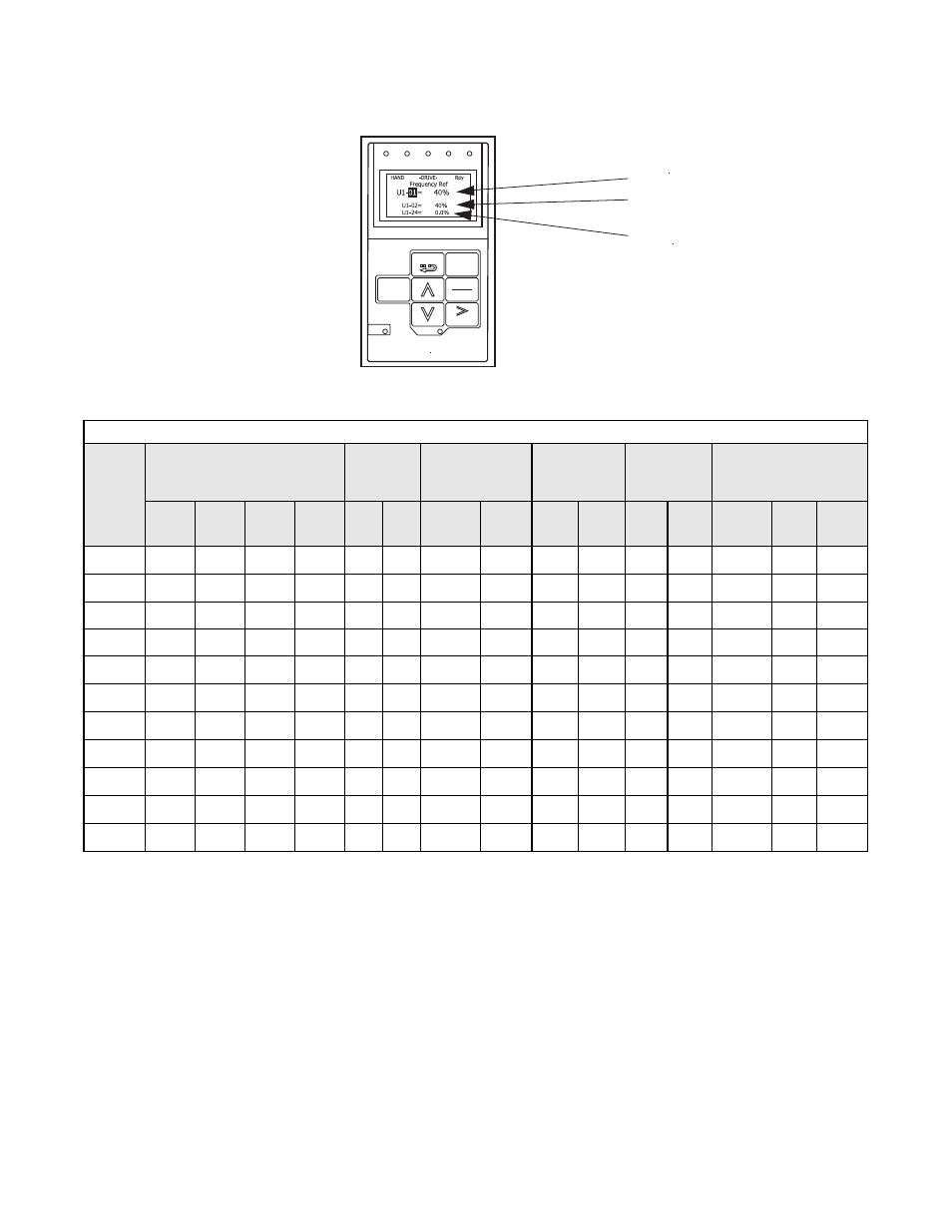
When the HAND/OFF/AUTO switch is transfered to the HAND position, the display will automatically change to indicate the
speed command, as in Figure 5.15.
Fig 5.15 Drive Display for PI Control, HAND Mode
Definitions:
L = LonWorks Option Card
* = The factory
default
S = Speed Potentiometer
# = The H/O/A switch must be in the AUTO position
J = Native Protocols (N2 or P1)
to allow serial com. or the PI function to control the Drive.
@= Jumpers required from S5 to S6
Parameter Reference:
b1-01:
Speed Command Input Source
H1-04:
Terminal S6 Function Selection
0: Operator
4: Multi-Step Ref 2
1: Terminals
6C: Com/Inv Sel 2
2: Serial Com (RS485)
6D: Auto Mode Selection
6E: Hand Mode Selection
H1-03:
Terminal S5 Function Selection
19: PI Disable
6C: Com/Inv Sel 2
19: PI Disable
H3-08:
Terminal A2 Signal Level
0: 0 - 10 VDC
2: 4 - 20 mA
Note:
Hand mode run/stop for Drive and Bypass is always via the front control panel HAND/OFF/AUTO switch.
Table 5.4 Option Dependent Drive PI Control Parameters in Bypass Units
Options
Parameters Effected by
Options Specified
Drive PCB
Switch S1
Resulting Hand
Speed Com-
mand Source
Auto: PI
Feedback
Terminal A2
Auto:
Run/Stop
Auto: PI Setpoint
b1-01 H1-03 H1-04 H3-08
1
2
Keypad
U1-01
Speed
Pot.
4-20
mA
0-10
VDC
TB1
3&4
Serial
#
Keypad
U1-01
Serial
#
Speed
Pot.
None
0
19
4*
2*
Off
On*
X
X
X
X
None
0
19
4
0
Off* Off
X
X
X
X
S
1*
19
4
0
Off
Off
X
X
X
X
S
1
19
4
2
Off
On
X
X
X
X
S
1
19
6D
@
0
Off
Off
X
X
X
X
J
2
19
6E
@
0
Off
Off
X
X
X
X
J
0
19
6C
@
0
Off
Off
X
X
X
X
J
0
19
6C
@
2
Off
On
X
X
X
X
L
0
6C
@
19
2
On
On
X
X
X
X
J and S
1
19
6C
@
0
Off
Off
X
X
X
X
L and S
1
6C
@
19
0
On
Off
X
X
X
X
FWD
REV
SEQ
REF ALARM
AUTO
RUN
Monitor
DATA
ESC
MENU
ENTER
RESET
STOP
SPEED COMMAND
- - - - - - - - - - - - - - - - - - - - - - - - - - - - -
OUTPUT
FEEDBACK