Bypass control circuit terminal functions, Table 2.6 bypass control circuit terminals, Electrical installation 2 - 15 – Yaskawa E7B Drive Bypass User Manual
Page 53
Electrical Installation 2 - 15
Bypass Control Circuit Terminal Functions
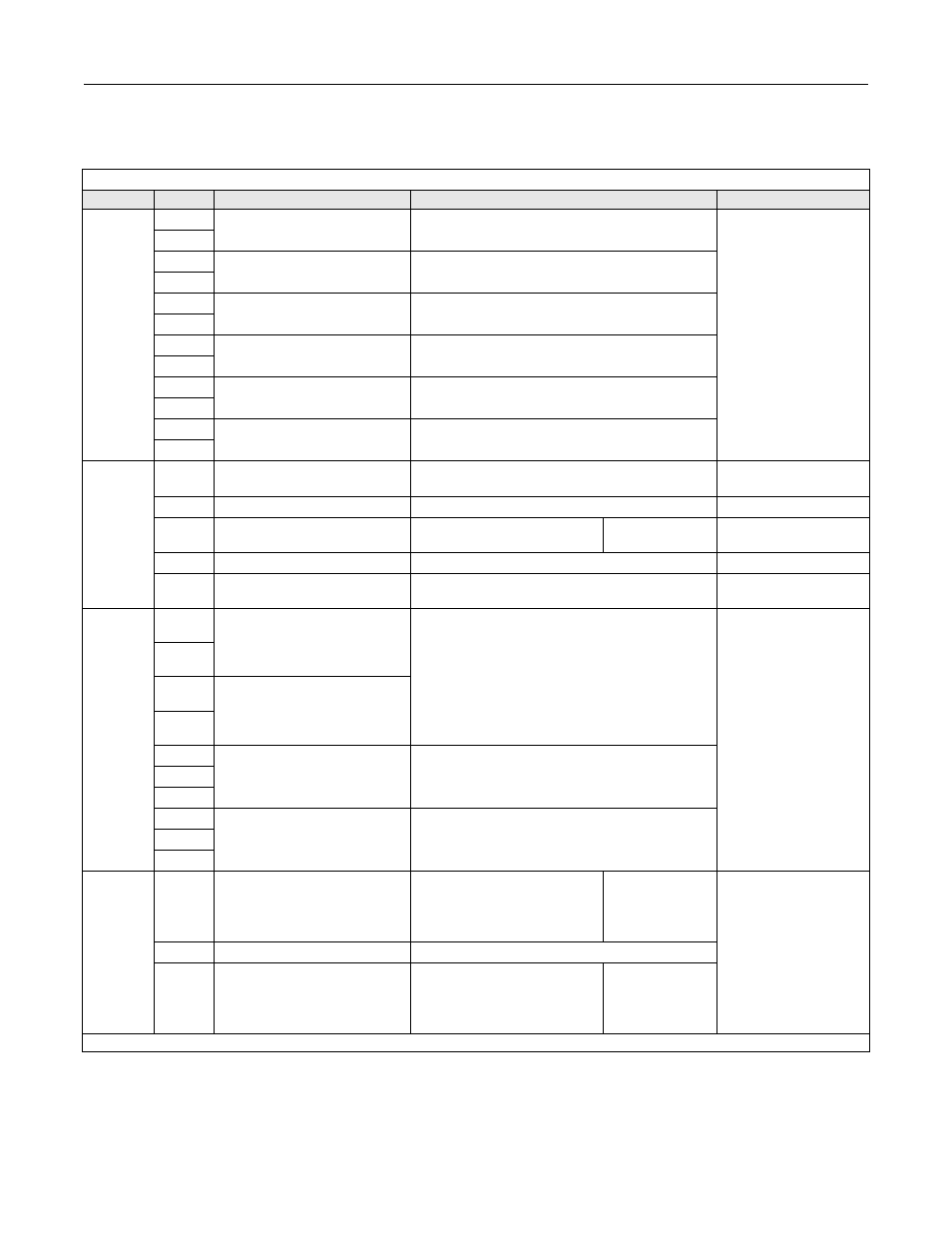
The functions of the control circuit terminals are shown in Table 2.6.
Table 2.6 Bypass Control Circuit Terminals
Type
No.
Signal Name
Function
Signal Level
Digital
input
signals
TB1-3
Auto Mode run/stop command
Run when CLOSED; stopped when OPEN.
Dry
Contacts
TB1-4
TB1-1
NC Safety Circuit
Fault when OPEN
TB1-2
TB1-5
BAS Interlock
Enable Drive when Closed
TB1-6
TB1-17
Smoke Purge
*Transfer to Bypass when Closed
TB1-18
TB1-23
2 Motor “OR”
*Transfer to Motor 2 When Closed
TB1-24
TB1-25
Remote Transfer
*Transfer to Bypass when Closed
TB1-26
Analog
input
signals
(Drive)
+V
+15 VDC power supply
+15 VDC power supply for analog Transmitters
+15 VDC
(Max. current: 20 mA)
A1
Analog Input or Speed Command
0 to +10 VDC/100%
0 to +10 V(20 k
Ω)
A2
Multi-function analog input
4 to 20 mA/100%
0 to +10 VDC/100% (H3-08)
Function set by
H3-09.
4 to 20 mA(250
Ω)
0 to +10 V(20k
Ω)
AC
Analog input common
–
–
E(G)
Shield wire, optional ground line
connection point
–
–
Digital
output
signals
TB1-7
Running on Drive
CLOSED During Operation
Dry contacts
Contact capacity:
1 A max. at 250 VAC
1 A max. at 30 VDC
TB1-8
TB1-9
Running on Bypass
TB1-10
TB1-11
Drive Fault
11/12 CLOSED During Fault Condition
12/13 OPEN During Fault Condition
TB1-12
TB1-13
TB1-14
Motor Overload or
Safety Circuit Fault
14/15 OPEN During Fault Condition
15/16 CLOSED During Fault Condition
TB1-15
TB1-16
Analog
output
signals
(Drive)
FM
Multi-function analog output
Frequency Output
0 to +10 VDC/100% frequency
Multi-function
analog monitor 1
Function set by
H4-01
0 to +10 VDC max. ±5%
2 mA max.
AC
Analog output common
–
AM
Multi-function analog output
Current Monitor
0 to +10 VAC/100%
Drive's rated current
Multi-function
analog monitor 2
Function set by
H4-04
* Switch Selectable Options