Bypass diagnostics, Troubleshooting the bypass printed circuit boards, Diagnostic & troubleshooting 6 - 2 – Yaskawa E7B Drive Bypass User Manual
Page 182
Diagnostic & Troubleshooting 6 - 2
Bypass Diagnostics
Troubleshooting the Bypass Printed Circuit Boards
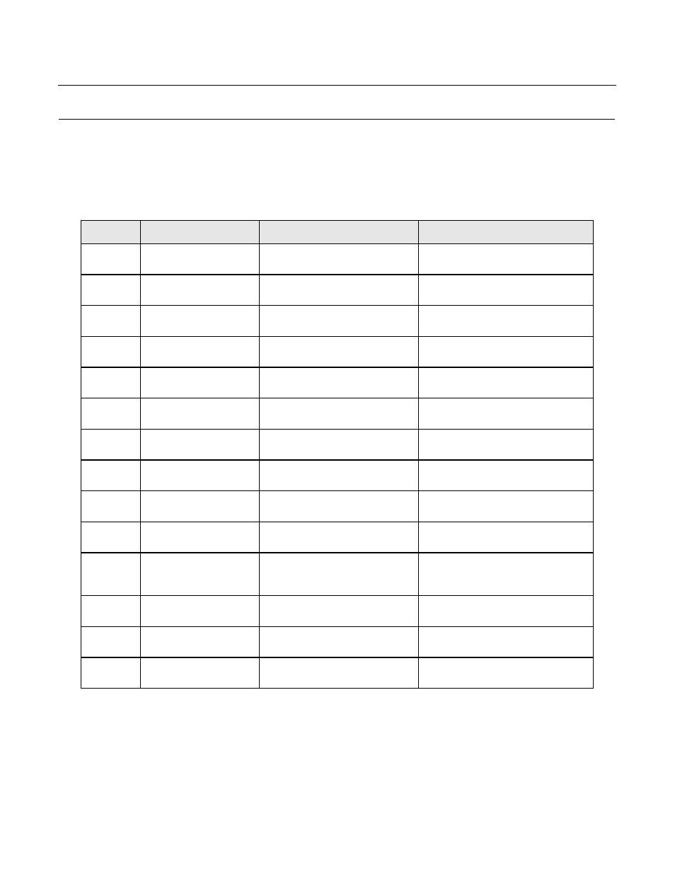
In order to check the two circuit boards (PCB A2 and A3 on the schematic diagram in Chapter 2) based on the following table,
it is assumed that they are assembled and wired in the unit and all the Bypass functions were working properly prior to
the fault.
No.
Fault Description
Possible Cause
Corrective Procedure
1
No lights, some/no
contactors pick up
Control circuit fuses are blown
Check for any short circuits before
replacing the fuses
2
No. 1 but fuses are not
blown
Power/wiring is disrupted to cabinet
and/or transformer
Check the power to the control
transformer/cabinet
3
No. 2 but power has no
problem
The Ribbon cable and/or Operator
(A3) board are faulty
Check for the cause/shorting before
ordering replacement
4
No. 3 but Operator (A3)
board and ribbon cable OK
The wiring to Relay (A2) board is
loose/Relay board faulty
Inspect the wiring/connectors to relay
board before ordering replacement
5
Power light on, contactors
do not pick up
Control circuit fuses are blown
Check for any short circuits/wiring before
replacing the fuses
6
No. 5 but fuses are not
blown
User connections to TB1 are
disrupted
Inspect connections to TB1
7
No. 6 but TB1 connections
are secure
The contactors/wiring are
faulty/disrupted
Inspect contactors and check the power at
the contactor
8
No. 7 but wiring and
contactors OK
The wiring to Relay (A2) board is
loose/Relay board faulty
Inspect the wiring/connectors to relay
(A2) board before ordering replacement
9
Contactor/blowers pick up
with delay
Bad connection/relays, loose circuit
boards
Check TB1 wiring/PCB ribbon cable
sockets before ordering replacement
10
Some options do not work
anymore
Loose wiring/connectors on Relay
(A2) and/or Operator (A3) boards
Inspect the Relay (A2) board
wiring/connectors/jumpers
11
Any light off but functions
are right
Bad light module, loose Operator
(A3) board/cable
Read 8-12 VAC voltage on Operator
board light pins before ordering
replacement
12
User functions on TB1
terminals 7 to 16 faulty
Bad user wiring, shorting to TB1
terminals, bad relays
Check the wiring and terminals on TB1
before ordering replacement
13
Auto/Remote/Purge
Functions faulty
Loose wiring on TB1, bad switches
of Relay (A2) board
Inspect wiring/Relay board switches,
TB1 inputs before ordering replacement
14
Drive/Damper Solenoid
does not operate
Loose wiring on Drive terminals,
incomplete TB1 connections
Inspect Drive wiring, TB1 connections