Devicenet™ simplified start-up procedure, Table 2: devicenet terminal block connections, Fig. 2 devicenet dip switch settings – Yaskawa DeviceNet Option Card CM059 User Manual
Page 11
11
DeviceNet™ Simplified Start-up Procedure
The following is a quick reference guide to install and configure the drive’s option. For more details, please refer to the drive’s
DeviceNet Technical Manual sections referenced.
1. Verify that the drive functions properly without the option installed. This includes running the drive from the operator
keypad, without communications.
2. Turn off the drive power supply and wait for at least 1 minute for the charge lamp to be completely out before
removing the operator and front cover. Remove the option hold-down tab on the left side of the drive case by
carefully compressing the top and bottom until it becomes free of its holder. Lift it out.
3. Install the option onto the drive. Mount the DeviceNet unit onto the drive making sure to connect 2CN securely. Replace
the option hold-down. Install the operator keypad and front cover back onto the unit after securing the DeviceNet unit
with screw.
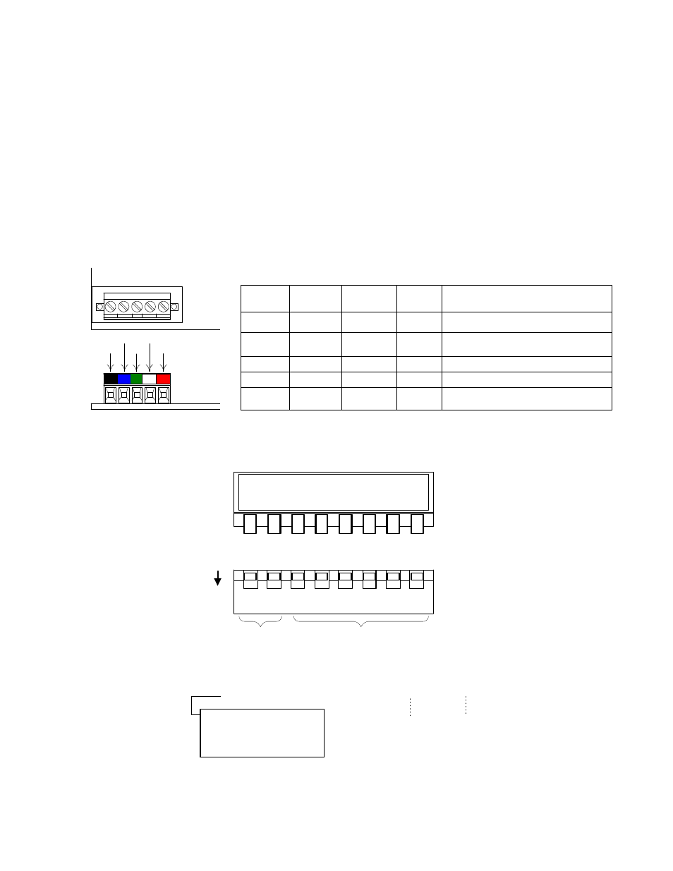
4. Connect the DeviceNet communication wires to the screw terminals on the option.
5. Using the DIP switch bank on the DeviceNet option kit, set communication baud rate (switch 1, 2) and MAC ID
(switch 3 – 8). Be sure to verify that no devices on the network have duplicate MAC IDs.
1
2
3
4
5
B K B L
W H R D
G R
BL WH
BK GR RD
Table 2: DeviceNet Terminal Block Connections
Terminal
No.
Terminal
Color
Name
Wiring
Color
Content
1
Black
V-
Black
Communication power supply GND
2
Blue
CAN_L
Blue
Communication data low side
3
Green
Shield
Bare
Shield wire
4
White
CAN_H
White
Communication data high side
5
Red
V+
Red
Communication power supply +24V
dc
ON
OFF
1
2
3
4
5
6
7
8
Baud Rate
1 2
OFF OFF 125kbps
OFF
ON
250kbps
ON
OFF 500kbps
ON ON
Not Allowed
MAC ID
3 4 5 6 7 8
OFF OFF OFF OFF OFF OFF 0
OFF OFF OFF OFF OFF
ON
1
OFF OFF OFF OFF
ON
OFF 2
OFF OFF OFF OFF
ON
ON
3
ON ON ON ON ON
OFF 62
ON ON ON ON ON ON
63
Note: Setting the “Not Allowed”
baud rate configuration
(Switch 1 and 2 “ON”)
causes a “BUS” fault on
the Digital Operator.
Fig. 2 DeviceNet DIP Switch Settings
DR
1
DR
0
ADR
5
ADR
4
ADR
3
ADR
2
ADR
1
ADR
0
1 2 3 4
8
5 6 7