Yaskawa V7 Drives User Manual
Page 96

5-44
Continued
E.
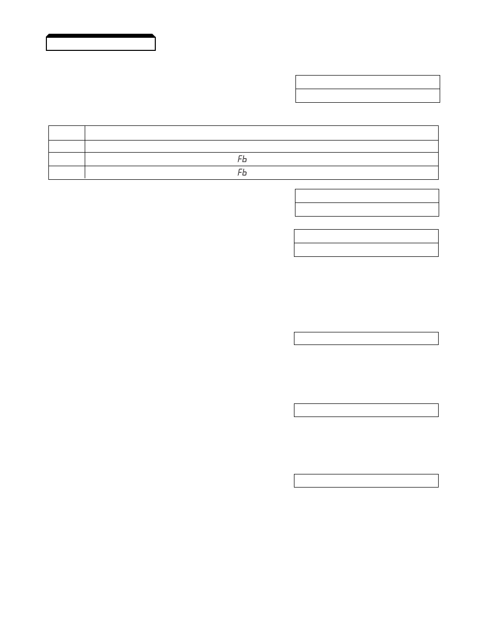
Feedback Loss Detection
n136: Feedback Loss Detection Selection
Factory setting:
0
Range: 0 to 2
n137: Feedback Loss Detection Level (PID)
Factory setting:
0
Range: 0 to 100 %
n138: Feedback Loss Detection Delay Time (PID)
Factory setting:
1.0
Range: 0.0 to 25.5
When feedback loss detection is enabled (
n136 = data "1" or "2"), the drive will detect if the
feedback signal falls below the
n137 level for more than the n138 delay time and respond according
to the setting of
n136.
F.
Multi-Function Input Terminals
n050 thru n056: Multi-function Inputs
Data
23 : PID Control Off
(Term. S1 thru S6)
By programming data "23" into one of the multi-function input parameters (
n050 thru n056), the
corresponding multi-function input terminal (S1 thru S6) will disable the PID control. At the same
time the PID setpoint will become the output frequency and the PID’s integrator will reset to zero.
n050 thru n056: Multi-function Inputs
Data
24 : PID Integral Reset
(Term. S1 thru S6)
By programming data "24" into one of the multi-function input parameters (
n050 thru n056), the
corresponding multi-function input terminal (S1 thru S6) will immediately reset the integrator’s value
to zero.
n050 thru n056: Multi-function Inputs
Data
25 : PID Integral Hold
(Term. S1 thru S6)
By programming data "25" into one of the multi-function input parameters (
n050 thru n056), the
corresponding multi-function input terminal (S1 thru S6) will hold the integrator’s output value.
When the contact is closed (on the Multi-Function Input Terminal), whatever value the integrator is
outputting will remain the same until the contact is opened.
5.28 PID CONTROL
Setting
Description
0
Feedback loss detection is disabled
1
Feedback loss detection is enabled –
alarm only (drive continues running)
2
Feedback loss detection is enabled –
fault (drive coasts to stop)
