14 modbus control, Modbus control -16 – Yaskawa V7 Drives User Manual
Page 68
5-16
The Drive can perform serial communication by using a programmable controller (PLC) and
MODBUS
®
protocol. Modbus is composed of one master PLC and 1 to 31 (maximum) slave units
(Drives). In serial communication between the master and slaves, the master always starts
transmission and the slaves respond to it.
The master communicates with one slave at a time. Address numbers are assigned to each slave in
advance, and the master specifies an address to communicate with. The slave which receives the
command from the master executes the function, and then responds to the master.
A.
Communication Specifications
• Interface
: RS-485 & RS-422
• Synchronization
:
Asynchronous
• Transmission parameters
:
Baud rate
— Selectable from 2400, 4800,
9600, 19,200 BPS (
n154)
Data length
— Fixed to 8 bits
Parity
— Parity / no parity, even / odd
selectable (
n155 )
Stop bit
— Fixed to 1 bit
• Protocol
:
Modbus
• Maximum number to units
to be connected
:
31 units
B.
Setting up the Modbus
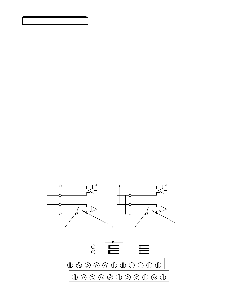
Terminals S+, S-, R+, and R- are used for modbus communications. A terminating resistor can be
enabled between R+ and R- by setting SW2 (1) to “on.” SW2 is found just above the upper row of
control circuit terminals. SW2 consists of two separate switches, the switch towards the top (labeled
“1”) turns on and off the terminating resistor.
The terminating resistor should only be enabled on the drive farthest away from the master.
5.14 MODBUS CONTROL
S+
S–
R+
SW2
OFF
ON
V
I
RS-422
TERMINAL RESISTOR (1/2W, 120
Ω)
SW2
R–
SW1
SW2
12
OFF
PNP
NPN
S+
S–
R+
SW2
RS-485
SW2
R–
TERMINAL RESISTOR (1/2W, 120
Ω)