Table 5, Figure 7, 5 installation procedure – Yaskawa APOGEE FLN P1 User Manual
Page 19
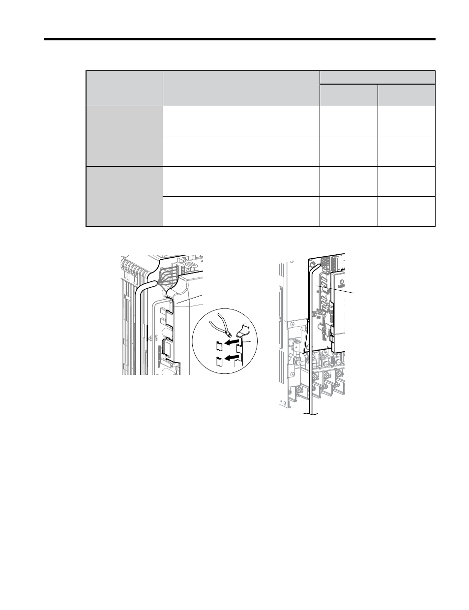
Table 5 Communication Wire Routing Selection
Drive Series
Model
Wire Routing <1>
Through
Front Cover
Inside Drive
P1000
CIMR-PU2A0004 to 0040;
CIMR-PU4A0002 to 0023;
CIMR-PU5A0003 to 0011
-
CIMR-PU2A0056 and above;
CIMR-PU4A0031 and above;
CIMR-PU5A0023 and above
-
(B)
iQpump1000
CIMR-PW2A0004 to 0040;
CIMR-PW4A0002 to 0023;
CIMR-PW5A0003 to 0011
-
CIMR-PW2A0056 and above;
CIMR-PW4A0031 and above;
CIMR-PW5A0023 and above
-
(B)
for examples of the different wire routing techniques.
A
B
A – Route wires through the
openings provided on the
left side of the front
cover.
<1>
B – Use the open space
provided inside the drive
to route option wiring.
Figure 7 Wire Routing Examples
<1> The drive will not meet NEMA Type 1 requirements if wiring is exposed outside the enclosure.
2.
Connect the network communication cables to the option modular connector terminal
block (TB1).
Note:
Separate the communications cables from the main circuit cables and other wiring and power
cables. Use properly grounded shielded cables for the communication cables to prevent
problems caused by electrical interference.
5 Installation Procedure
YASKAWA TOEP YAICOM 13 Metasys N2 & Apogee FLN P1 SI-J3 Installation & Technical Manual
19