Installing the option, 5 installation procedure – Yaskawa APOGEE FLN P1 User Manual
Page 15
I
J
K
M
A
L
D
F
G
C
E
B
H
NS
MS
NS
MS
TX
RX
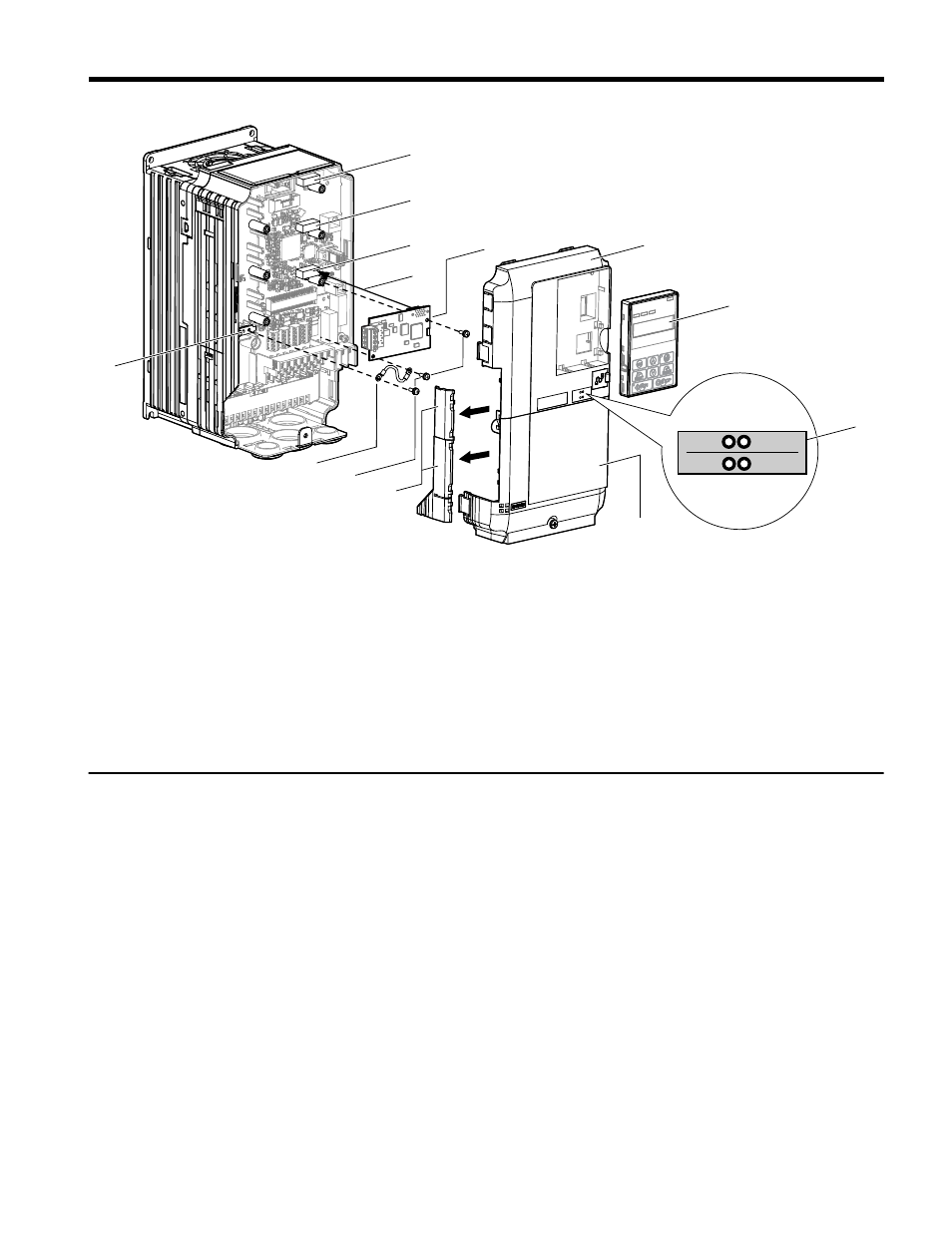
A – Drive front cover
B – Digital operator
C – LED label
D – Drive terminal cover
E – Removable tabs for wire
routing
F – Included screws
G – Ground wire
H – Drive grounding terminal
(FE)
I – Connector CN5-C
J – Connector CN5-B
K – Connector CN5-A
L – Insertion point for CN5
connector
M – SI-J3 option
Figure 2 Drive Components with Option
u
Installing the Option
Remove the front covers of the drive before installing the option. Refer to the drive Quick
Start Guide for directions on removing the front covers. Cover removal varies depending on
drive size. This option can be inserted only into the CN5-A connector located on the drive
control board.
Preparing the Drive
1.
Shut off power to the drive, wait the appropriate amount of time for voltage to
dissipate, then remove the digital operator (B) and front covers (A, D). Front cover
removal varies by model.
DANGER! Electrical Shock Hazard. Do not connect or disconnect wiring while the power is on.
Failure to comply will result in death or serious injury. Before installing the option, disconnect all
power to the drive. The internal capacitor remains charged even after the power supply is turned
off. The charge indicator LED will extinguish when the DC bus voltage is below 50 Vdc. To prevent
electric shock, wait at least five minutes after all indicators are off and measure the DC bus voltage
level to confirm safe level.
5 Installation Procedure
YASKAWA TOEP YAICOM 13 Metasys N2 & Apogee FLN P1 SI-J3 Installation & Technical Manual
15