I.9 parameter table – Yaskawa iQpump Micro Quick Start User Manual
Page 96
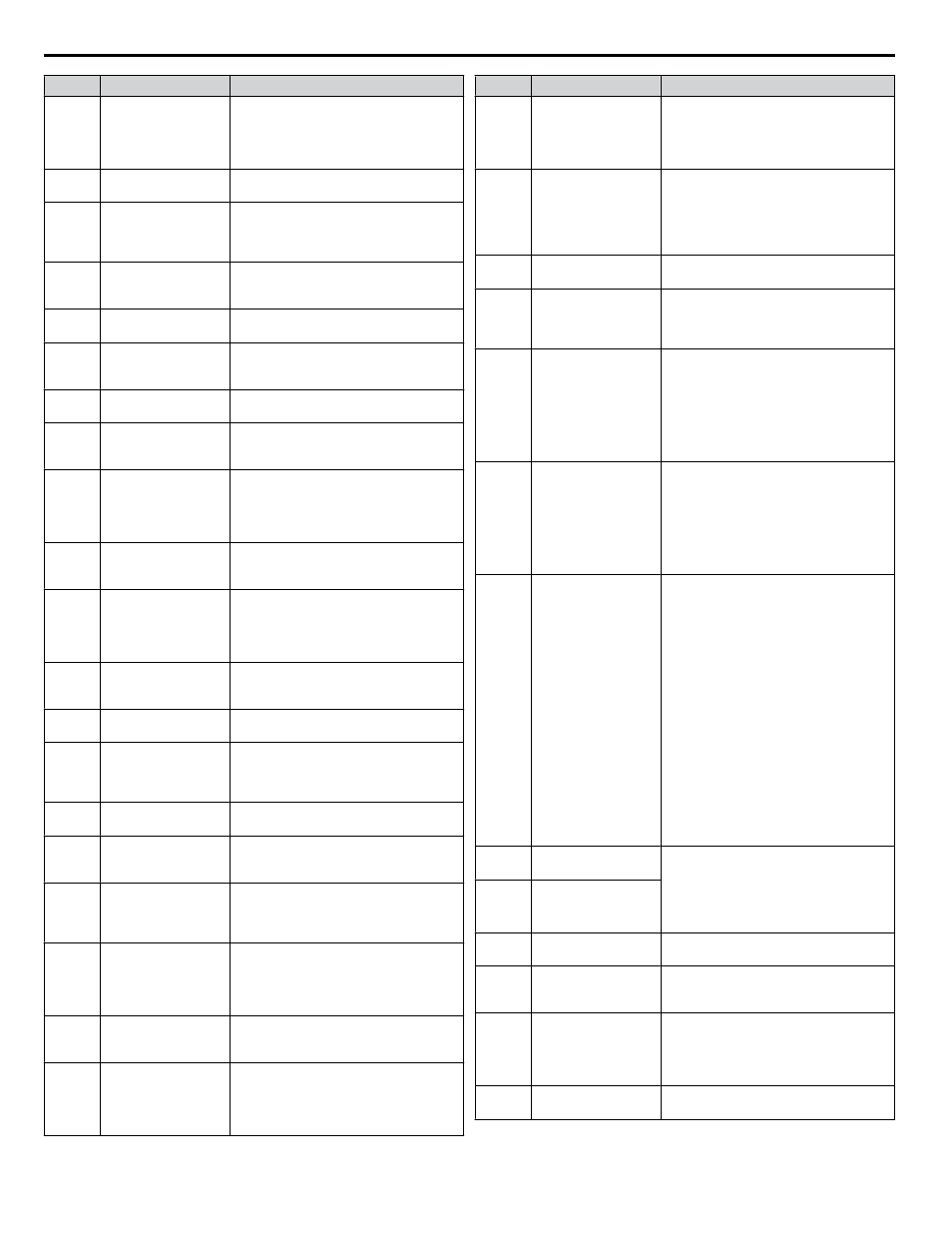
No.
Name
Description
L8-07
Output Phase Loss
Protection Selection
0: Disabled
1: Enabled (triggered by a single phase
loss)
2: Enabled (triggered when two phases are
lost)
L8-09
Output Ground Fault
Detection Selection
0: Disabled
1: Enabled
L8-10
Heatsink Cooling Fan
Operation Selection
0: During run only. Fan operates only
during run for L8-11 seconds after stop.
1: Fan always on. Cooling fan operates
whenever the drive is powered up.
L8-11
Heatsink Cooling Fan
Off Delay Time
Sets a delay time to shut off the cooling fan
after the Run command is removed when
L8-10 = 0.
L8-12
Ambient Temperature
Setting
Enter the ambient temperature. This value
adjusts the oL2 detection level.
L8-15
oL2 Characteristics
Selection at Low
Speeds
0: No oL2 level reduction below 6 Hz.
1: oL2 level is reduced linearly below 6
Hz. It is halved at 0 Hz.
L8-18
Software Current Limit
Selection
0: Disabled
1: Enabled
L8-19
Frequency Reduction
Rate during Overheat
Pre-Alarm
Specifies the frequency reference reduction
gain at overheat pre-alarm when L8-03 = 4.
L8-35
Installation Method
Selection
0: IP00/Open-Chassis enclosure
1: Side-by-Side mounting
2: IP20/NEMA Type 1 enclosure
3: Finless model drive or external heatsink
installation
L8-38
Carrier Frequency
Reduction
0: Disabled
1: Enabled below 6 Hz
2: Enabled for the entire speed range
L8-40
Carrier Frequency
Reduction Off Delay
Time
Sets the time that the drive continues
running with reduced carrier frequency
after the carrier reduction condition is gone.
Setting 0.00 s disables the carrier frequency
reduction time.
L8-41
High Current Alarm
Selection
0: Disabled
1: Enabled. An alarm is triggered at output
currents above 150% of drive rated current.
n1-01
Hunting Prevention
Selection
0: Disabled
1: Enabled
n1-02
Hunting Prevention
Gain Setting
If the motor vibrates while lightly loaded,
increase the gain by 0.1 until vibration
ceases. If the motor stalls, decrease the gain
by 0.1 until the stalling ceases.
n1-03
Hunting Prevention
Time Constant
Sets the time constant used for Hunting
Prevention.
n1-05
Hunting Prevention
Gain while in Reverse
Sets the gain used for Hunting Prevention.
If set to 0, the gain set to n1-02 is used for
operation in reverse.
n3-13
Overexcitation
Deceleration Gain
Applies a gain to the V/f pattern during
deceleration (L3-04 = 4). Returns to normal
values after ramp to stop or at re-
acceleration.
n3-21
High-Slip Suppression
Current Level
Sets output current level at which the drive
will start reducing the overexcitation gain
in order to prevent a too high motor slip
during Overexcitation Deceleration. Set as
a percentage of the drive rated current.
n3-23
Overexcitation
Operation Selection
0: Enabled in both directions
1: Enabled only when rotating forward
2: Enabled only when in reverse
o1-01
Drive Mode Unit
Monitor Selection
Selects the content of the last monitor that
is shown when scrolling through Drive
Mode display. Enter the last three digits of
the monitor parameter number to be
displayed: Uo-oo.
No.
Name
Description
o1-02
User Monitor Selection
after Power Up
1: Frequency reference (U1-01)
2: Direction
3: Output frequency (U1-02)
4: Output current (U1-03)
5: User-selected monitor (set by o1-01)
o1-03
Digital Operator
Display Selection
0: 0.01 Hz
1: 0.01% (100% = E1-04)
2: r/min (calculated using the number of
motor poles setting in E2-04)
3: User-selected units (set by o1-09, o1-10
and o1-11)
o1-05
LCD Contrast Control Sets the brightness of the optional LCD
operator.
o1-06
User Monitor Selection
Mode
0: 3 Monitor Sequential (displays the next
two sequential monitors)
1: 3 Monitor Selectable (set by o1-07 and
o1-08)
o1-07
Second Line Monitor
Selection
Selects the monitor that is shown in the
second line.
Enter the last three digits of the monitor
parameter number to be displayed: Uo-
oo. For example, set "403" to display
monitor parameter U4-03.
Note: Parameter is effective only when
o1-06 is set to 1.
o1-08
Third Line Monitor
Selection
Selects the monitor that is shown in the third
line.
Enter the last three digits of the monitor
parameter number to be displayed: Uo-
oo. For example, set "403" to display
monitor parameter U4-03.
Note: Parameter is effective only when
o1-06 is set to 1.
o1-09
Frequency Reference
Display Units
Sets unit display for the frequency reference
parameters and frequency related monitors
when o1-03 = 3.
0: WC (Inch of water)
1: PSI (Pounds per square inch)
2: GPM (Gallons per minute)
3: F (Degrees Fahrenheit)
4: CFM (Cubic feet per minute)
5: CMH (Cubic meters per hour)
6: LPH (Liters per hour)
7: LPS (Liters per second)
8: Bar (Bar)
9: Pa (Pascal)
10: C (Degrees Celsius)
11: Mtr (Meters)
12: Ft (Feet)
13: LPM (Liters per minute)
14: CMM (Cubic meters per minute)
15: “Hg (inches of mercury)
25: None
o1-10
User-Set Display Units
Maximum Value
These settings define the display values
when o1-03 is set to 3.
o1-10 sets the display value that is equal to
the maximum output frequency.
o1-11 sets the position of the decimal
position.
o1-11
User-Set Display Units
Decimal Display
o1-12
Home Help Text
0: Disabled
1: Enabled
o2-02
STOP Key Function
Selection
0: Disabled. STOP key is disabled in
REMOTE operation.
1: Enabled. STOP key is always enabled.
o2-03
User Parameter
Default Value
0: No change.
1: Set defaults. Saves parameter settings as
default values for a User Initialization.
2: Clear all. Clears the default settings that
have been saved for a User Initialization.
o2-04
Drive Model Selection Enter the drive model. Setting required only
if installing a new control board.
i.9 Parameter Table
96
YASKAWA TOEP YAIQPM 02B YASKAWA AC Drive - iQpump Micro Quick Start Guide