I.9 parameter table – Yaskawa iQpump Micro Quick Start User Manual
Page 92
No.
Name
Description
C3-03
Slip Compensation
Limit
Sets an upper limit for the slip
compensation function as a percentage of
motor rated slip for motor 1 (E2-02).
C3-04
Slip Compensation
Selection during
Regeneration
0: Disabled
1: Enabled above 6 Hz
C4-01
Torque Compensation
Gain
Sets the gain for the automatic torque
(voltage) boost function and helps to
produce better starting torque. Used for
motor 1.
C4-02
Torque Compensation
Primary Delay Time 1 Sets the torque compensation filter time.
C6-02
Carrier Frequency
Selection
1: 2.0 kHz
2: 5.0 kHz (4.0 kHz)
3: 8.0 kHz (6.0 kHz)
4: 10.0 kHz (8.0 kHz)
5: 12.5 kHz (10.0 kHz)
6: 15.0 kHz (12.0 kHz)
7: Swing PWM1 (Audible sound 1)
8: Swing PWM2 (Audible sound 2)
9: Swing PWM3 (Audible sound 3)
A: Swing PWM4 (Audible sound 4)
B: Leakage Current Rejection PWM
C to E: No setting possible
F: User-defined (determined by C6-03
through C6-05)
C6-03
Carrier Frequency
Upper Limit
Determines the upper and lower limits for
the carrier frequency.
C6-04
Carrier Frequency
Lower Limit
C6-05
Carrier Frequency
Proportional Gain
d1-01 to
d1-16
Frequency Reference 1
to 16
Sets the frequency reference for the drive.
Setting units are determined by parameter
o1-03.
d1-17
Jog Frequency
Reference
Sets the Jog frequency reference. Setting
units are determined by parameter o1-03.
d2-01
Frequency Reference
Upper Limit
Sets the frequency reference upper limit as
a percentage of the maximum output
frequency.
d2-02
Frequency Reference
Lower Limit
Sets the frequency reference lower limit as
a percentage of the maximum output
frequency.
d2-03
Master Speed
Reference Lower Limit
Sets the lower limit for frequency
references from analog inputs as a
percentage of the maximum output
frequency.
d3-01
Jump Frequency 1
Eliminates problems with resonant
vibration of the motor/machine by avoiding
continuous operation in predefined
frequency ranges. The drive accelerates and
decelerates the motor through the
prohibited frequency ranges.
d3-02
Jump Frequency 2
d3-03
Jump Frequency 3
d3-04
Jump Frequency Width
Sets the dead-band width around each
selected prohibited frequency reference
point.
d4-01
Frequency Reference
Hold Function
Selection
0: Disabled. Drive starts from zero when
the power is switched on.
1: Enabled. At power up, the drive starts the
motor at the Hold frequency that was saved.
d4-03
Frequency Reference
Bias Step (Up/Down 2)
Sets the bias added to the frequency
reference when the Up 2 and Down 2 digital
inputs are enabled (H1-oo = 75, 76).
d4-05
Frequency Reference
Bias Operation Mode
Selection (Up/Down 2)
0: Bias value is held if no input Up 2 or
Down 2 is active.
1: When the Up 2 reference and Down 2
reference are both on or both off, the applied
bias becomes 0. The specified accel/decel
times are used for acceleration or
deceleration.
No.
Name
Description
d4-06
Frequency Reference
Bias (Up/Down 2)
The Up/Down 2 bias value is saved in d4-06
when the frequency reference is not input
by the digital operator. Set as a percentage
of the maximum output frequency.
d4-07
Analog Frequency
Reference Fluctuation
Limit (Up/Down 2)
Limits how much the frequency reference
is allowed to change while an input terminal
set for Up 2 or Down 2 is enabled.
d4-08
Frequency Reference
Bias Upper Limit (Up/
Down 2)
Sets the upper limit for the bias and the
value that can be saved in d4-06. Set as a
percentage of the maximum output
frequency.
d4-09
Frequency Reference
Bias Lower Limit (Up/
Down 2)
Sets the lower limit for the bias and the
value that can be saved in d4-06. Set as a
percentage of the maximum output
frequency.
d4-10
Up/Down Frequency
Reference Limit
Selection
0: The lower limit is determined by d2-02
or an analog input.
1: The lower limit is determined by d2-02.
E1-01
Input Voltage Setting
This parameter must be set to the power
supply voltage.
WARNING!Electrical Shock Hazard.
Drive input voltage (not motor voltage)
must be set in E1-01 for the protective
features of the drive to function properly.
Failure to do so may result in equipment
damage and/or death or personal injury.
E1-03
V/f Pattern Selection
0: 50 Hz, Constant torque 1
1: 60 Hz, Constant torque 2
2: 60 Hz, Constant torque 3 (50 Hz base)
3: 72 Hz, Constant torque 4 (60 Hz base)
4: 50 Hz, Variable torque 1
5: 50 Hz, Variable torque 2
6: 60 Hz, Variable torque 3
7: 60 Hz, Variable torque 4
8: 50 Hz, High starting torque 1
9: 50 Hz, High starting torque 2
A: 60 Hz, High starting torque 3
B: 60 Hz, High starting torque 4
C: 90 Hz (60 Hz base)
D: 120 Hz (60 Hz base)
E: 180 Hz (60 Hz base)
F: Custom V/f, E1-04 through E1-13
settings define the V/f pattern
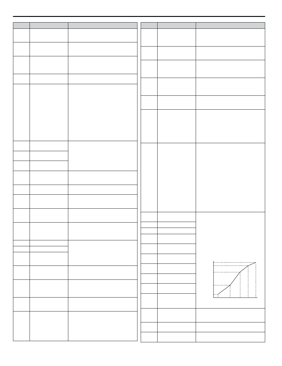
E1-04
Maximum Output
Frequency
These parameters are only applicable when
E1-03 is set to F.
To set linear V/f characteristics, set the
same values for E1-07 and E1-09.
In this case, the setting for E1-08 will be
disregarded. Ensure that the four
frequencies are set according to these rules:
E1-09 ≤ E1-07 < E1-06 ≤ E1-11 ≤ E1-04
Setting E1-11 to 0 disables both E1-11 and
E1-12 and the above conditions do not
apply.
Output Voltage (V)
Frequency (Hz)
E1-05
E1-12
E1-13
E1-08
E1-10
E1-09
E1-07 E1-06 E1-11 E1-04
E1-05
Maximum Voltage
E1-06
Base Frequency
E1-07
Middle Output
Frequency
E1-08
Middle Output
Frequency Voltage
E1-09
Minimum Output
Frequency
E1-10
Minimum Output
Frequency Voltage
E1-11
Middle Output
Frequency 2
E1-12
Middle Output
Frequency Voltage 2
E1-13
Base Voltage
E2-01
Motor Rated Current
Sets the motor nameplate full load current
in amps. Automatically set during
Auto-Tuning.
E2-02
Motor Rated Slip
Sets the motor rated slip. Automatically set
during Auto-Tuning.
E2-03
Motor No-Load
Current
Sets the no-load current for the motor.
Automatically set during Auto-Tuning.
i.9 Parameter Table
92
YASKAWA TOEP YAIQPM 02B YASKAWA AC Drive - iQpump Micro Quick Start Guide