Alarm detection, Alarm codes – Yaskawa iQpump Micro Quick Start User Manual
Page 81
Digital Operator
Display
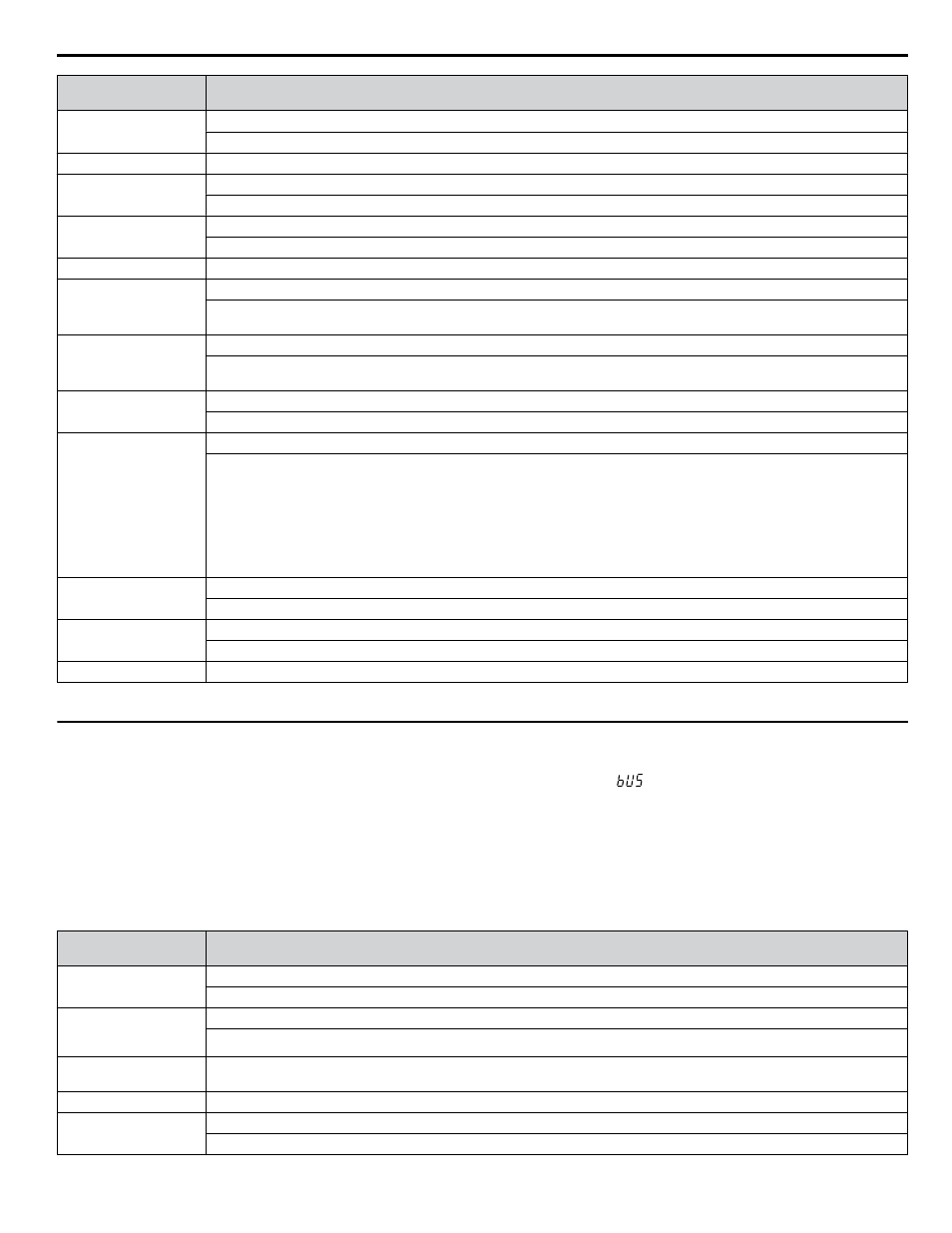
Fault Name
rr
Dynamic Braking Transistor
The built-in dynamic braking transistor failed.
SC
IGBT Short Circuit or Ground Fault
SEr
Too Many Speed Search Restarts
The number of Speed Search restarts exceeded the value set to b3-19.
Single Phase Foldback
(1PH)
Single Phase Foldback
Output speed is being limited because of excessive DC Bus voltage ripple.
TIE
Time Interval Error
UL3
Undertorque Detection 1
The current has fallen below the minimum value set for Torque Detection Level 1 (L6-02) for longer than the allowable time
(L6-03).
UL4
Undertorque Detection 2
The current has fallen below the minimum value set for Torque Detection Level 2 (L6-05) for longer than the allowable time
(L6-06).
UL6
Underload Det 6
Motor Underload
The load has fallen below the underload curve defined in L6-14.
Uv1
<1>
Control Circuit Undervoltage Fault
One of the following conditions occurred while the drive was running:
• Voltage in the DC bus fell below the undervoltage detection level (L2-05).
• For 200 V class: approximately 190 V (160 V for single phase drives)
• For 400 V class: approximately 380 V (350 V when E1-01 is less than 400) The fault is output only if L2-01 = 0 or L2-01
= 1 and the DC bus voltage is under L2-05 for longer than L2-02.
The fault is output only if L2-01 is set to 0 or 1 and the DC bus voltage has fallen below the level set to L2-05 for longer than
the time set to L2-02.
Uv2
<1>
Control Power Supply Voltage Fault
Voltage is too low for the control drive input power.
Uv3
<1>
Undervoltage 3 (Soft-Charge Bypass Relay Fault)
The soft-charge bypass relay failed.
VLTS
Volute-Thermostat Fault
<1> Fault history is not kept for this fault.
u
Alarm Detection
Note:
Digital operator display text is represented in the tables below using standard font for both LCD displays and LED displays. When using
the standard LED operator, however, display text will appear in 7-segment LED (ex: “
”). When the LED fault display differs from the
LCD display, the LED display text will be shown in parentheses under the LCD display text.
n
Alarm Codes
An alarm is indicated by a code on the data display and the flashing ALM LED. The drive output is not necessarily switched
off.
To remove an alarm, trace and remove the cause, and reset the drive by pushing the Reset key on the operator or cycle the
power supply.
Digital Operator
Display
Alarm Name
AEr
Station Address Setting Error (CC-Link, CANopen, MECHATROLINK)
Option card node address is outside of the acceptable setting range.
AnalogFB Lost
Switched to Net
(AFBL)
Analog Feedback Lost
Analog feedback has not been detected and the network PI feedback signal is now used.
Anti-Jam Active
(AJA)
Anti-Jam Alarm
bAT
Digital Operator Battery Voltage Low
bb
Baseblock
Drive output interrupted as indicated by an external baseblock signal.
i.7 Troubleshooting
YASKAWA TOEP YAIQPM 02B YASKAWA AC Drive - iQpump Micro Quick Start Guide
81