Dip switch s1 analog input signal selection, I.5 main circuit wiring – Yaskawa iQpump Micro Quick Start User Manual
Page 55
n
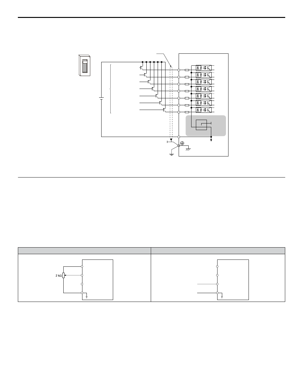
Transistor Input Signal Using +24 V Common/Source Mode
When controlling digital inputs by PNP transistors (+24 V common/sourcing mode), set the DIP switch S3 to SOURCE and
use an external 24 V power supply.
Forward run / stop
Reverse run / stop
External fault N.O.
Fault rest
Multi-step speed 1
Multi-step speed 2
Jog frequency
External
power supply
Shielded cable
Drive
Multi-function input
S1
S2
S3
+24V
S4
S5
S6
S7
SC
S3
SINK
SOURCE
+24 V
SINK
SOURCE
Figure i.22 Source Mode: Sequence from PNP Transistor (+24 V Common)
u
DIP Switch S1 Analog Input Signal Selection
The main frequency reference can either be a voltage or current signal input. For voltage signals both analog inputs, A1 and
A2, can be used, for current signals A2 must be used.
When using input A2 as a voltage input, set DIP switch S1 to “V” (left position) and program parameter H3-09 to 0 (0 to +10
Vdc with lower limit) or 1 (0 to +10 Vdc without lower limit).
To use current input at terminal A2, set the DIP switch S1 to "I" (default setting) and set parameter H3-09 = 2 or 3 (4-20 mA
or 0-20 mA). Set parameter H3-10 = 0 (frequency reference).
Note:
If Terminals A1 and A2 are both set for frequency reference (H3-02 = 0 and H3-10 = 0), the addition of both input values builds the frequency
reference.
Table i.13 Frequency Reference Configurations
Voltage Input
Current Input
Drive
Main speed
frequency reference
(voltage input)
Main speed
frequency reference
(current input)
Frequency reference
common
+10.5 V
20 mA current
0 to 10 V
+V
A1
A2
AC
Drive
Main speed
frequency reference
(voltage input)
Main speed
frequency reference
(current input)
Frequency reference
common
4 to 20 mA input
or
0 to 20 mA input
+10.5 V
20 mA current
+V
A1
A2
AC
i.5 Main Circuit Wiring
YASKAWA TOEP YAIQPM 02B YASKAWA AC Drive - iQpump Micro Quick Start Guide
55