1 configuration of the data readout – Yaskawa Ladder Works Programming Manual User Manual
Page 212
9.10 Inverter Constant Read Function (ICNS-RD)
9-37
Table 9.15 Configuration of Inverter Constant Read Execution Status (STASTUS)
Name Bit
No.
Remarks
System Reserved
Bit 0 to Bit 7
Execution sequence error
Bit8
The function will not be executed.
Transmission parameter error
Bit9
The function will not be executed.
Designated type error
Bit10
The function will not be executed.
Designated No. error
Bit11
The function will not be executed.
Error in number (amount) of the
designated data
Bit12
The function will not be executed.
Transmission error
Bit13
The function will not be executed.
Inverter response error
Bit14
The function will not be executed.
Address input error
Bit15
The function will not be executed.
Note : In the case of an inverter response error, the error codes from the inverter are indicated in bit0
to bit7.
01H(1) : function code error
02H(2) : reference No. error
Numbers in ( ) are of decimal expressions.
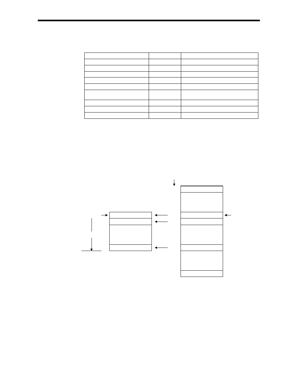
9.10.1 Configuration of the Data Readout
bn-01
ASR integration time
PG dividing ratio
・
・
・
・
bn-05
bn-14
Cns-No
Cns-Size
Constant data 10
・
・
・
・
Constant data 2
Constant data 1
User register
ASR proportional gain
・
・
・
・
AO optional output gain
・
・
・
・
Acceleration time 1
Inverter Constants
bn-25
bn-06
Cns-Typ
Dat-Adr