2 i/o module connection details, 1 connection between units, Figure 9.2.1.1 connection details of i/o module – Yaskawa YASNAC PC NC Connecting Manual User Manual
Page 82: Jznc-jfc10
9 - 3
YASNAC PCNC Connecting Manual
Chapter 9: Connection of I/O Module
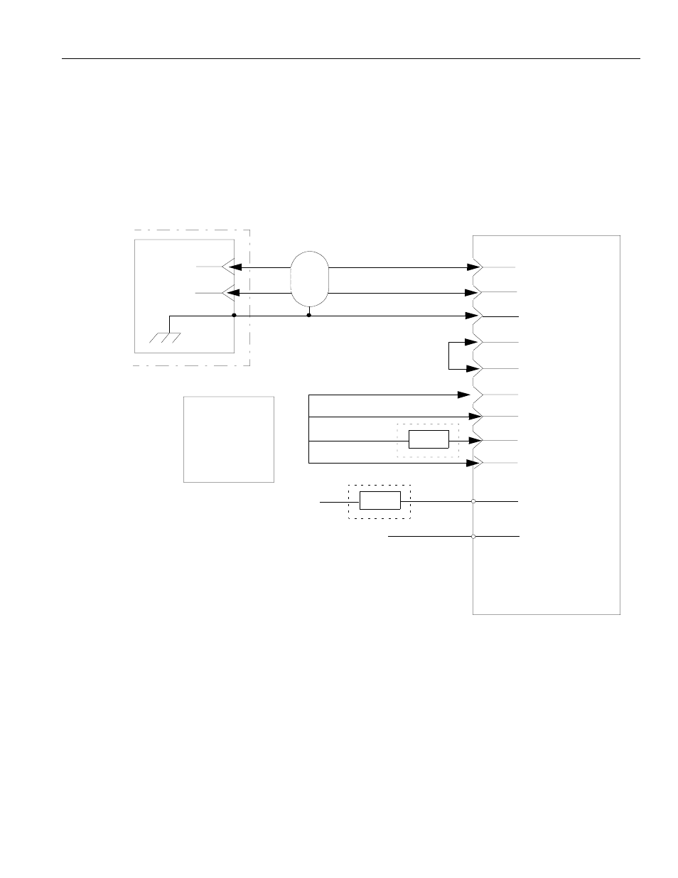
9.2 I/O Module Connection Details
This section describes the connection details between the CNC unit and the I/O module.
9.2.1
Connection between Units
If FC810, FC815 or FC860 is used, +24V of standard power supply unit is output to CN7-1
and CN7-2 terminals. Use the twisted-pair shielded cable with characteristic impedance of
120
Ω
for the signal cable of /SIG AND SIG signals.
Note: Without the power supply having overcurrent protection or overcurrent protection
countermeasure for output signal (Section 10.3.2 “I/O Circuit of I/O Port”), a fuse
should be installed in the +24V line for I/O overcurrent protection. As the required
capacity of the fuse changes depending on the I/O points, refer to Section 10.3.3
“Power Supply for I/O Signal” for details (e.g. A 7.5 Amp fuse is required for 112
inputs and 96 outputs).
CN02 (RIO)
2
3
CN11-1
S
SH
JANCD-FC810/FC815
/FC860/FC681
CN11-2
CN11-3
CN11-5
CN11-8
CN13-1
CN13-4
CN13-3
CN13-5
CN7-1
CN7-2
*S
Hood case
FG
Power Supply
+5V
0
5
V
+24V
0
24
V
FU
+24V
0
24
V
FU
(See note)
(See note)
Power supply unit output
JZNC-JFC10
(Only for FC810/FC815/FC860)
PCNC Unit
FIGURE 9.2.1.1 Connection Details of I/O Module