2 connection details, 1 connection between pcnc unit and servopack – Yaskawa YASNAC PC NC Connecting Manual User Manual
Page 67
6 - 3
YASNAC PCNC Connecting Manual
Chapter 6: Connection with the Servopack
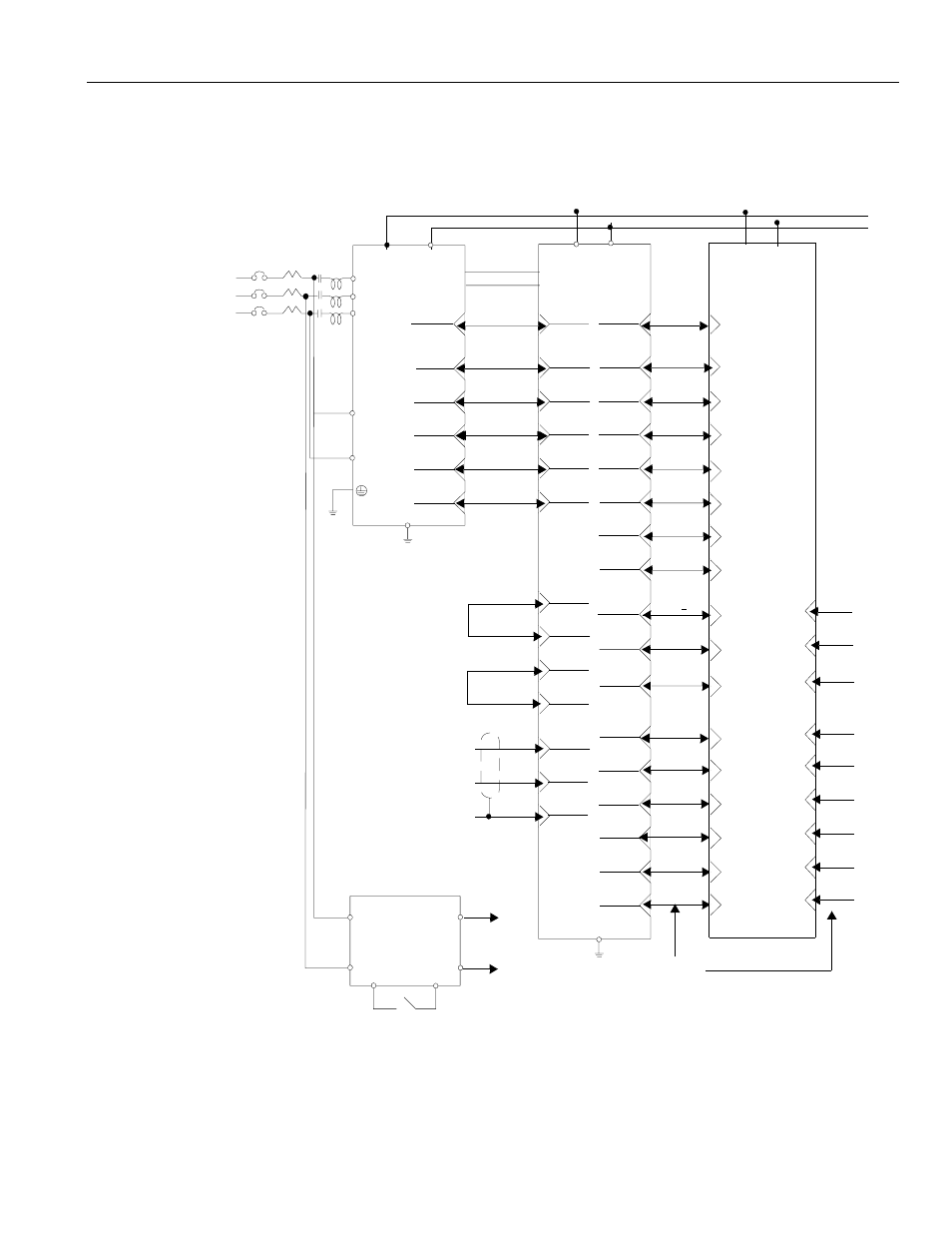
6.2 Connection Details
This section contains connection diagrams of the PCNC unit to the Servopack.
6.2.1
Connection Between PCNC Unit and Servopack
FIGURE 6.2.1.1 Connection between PCNC unit and Servopack
5CN-25 CONFLT 51CN-26 52CN-25 CONFLT 51CN-26 51CN-25
5CN-26 CONRDY 51CN-25 52CN-26 CONRDY 51CN-25 51CN-26
11 12 13 14 0V 11 12 13 14 11 12 13 14 0V 11 12 13 14 11 12 13 14
19 20 21 22 19 20 21 22 19 20 21 22 19 20 21 22 19 20 21 22
P+ N- P+ N- P+ N-
CIMR-MR5N CIMR-M5N SGDC-
AJA (No.1 axis)
R
R/L1
S
S/L2
T
T/L3
200/220/230
VAC
{
{
P1 P2
N1
N1
5 16 17 18 15 16 17 18 15 16 17 18 15 16 17 18 15 16 17 18
5CN- 51CN 52CN
5CN-24 AXRUN 51CN-23 52CN-24 AXRUN 51CN-23 51CN-24
5CN-23 CONRST 51CN-24 52CN-23 CONRST 51CN-24 51CN-23
3
Φ 1
MCCB 1MC L
Base plate
mounting screw
Always connect
For monitoring zero speed
for termination unit
52CN-33 +24VIN 51CN-34 52CN-33
52CN-32 ESPO 51CN-31 52CN-32
ALMC 1CN-8
52CN-30
ALM - 1CN-7
R 4CN-4
*S 4CN-6
PAO 1CN-13
* PAO 1CN-14
SS 1CN-17
Base plate
mounting screw
Brake power supply unit
O P R 1 0 9
1 3
2 4
5 6
To motor brake
ALM+ 51CN-29 52CN-30
52CN-28
52CN-27
52CN-29
52CN-31
52CN-5
52CN-3
52CN-6
52CN-4
ALMC 51CN-27 52CN-28
S
*S
/EXT1
/EXT2
ESP1
BAT+
BAT-
Flat cable
1,2,7,8,9,10 1,2,7,8,9,10 1,2,7,8,9,10
51CN-4 52CN-3
51CN-6 52CN-5
51CN-32 52CN-31
51CN-30 52CN-29
51CN-28 52CN-27
51CN-5 52CN-6
51CN-3 52CN-4
24 V
24 V
A2
A1
Converter unit
Inverter unit Servo unit