1 connection diagram, 2 names and description of main circuit terminals, 1 wiring for re-engineered ac servopacks cacr-sr – Yaskawa CACR-SRxxBF User Manual
Page 26
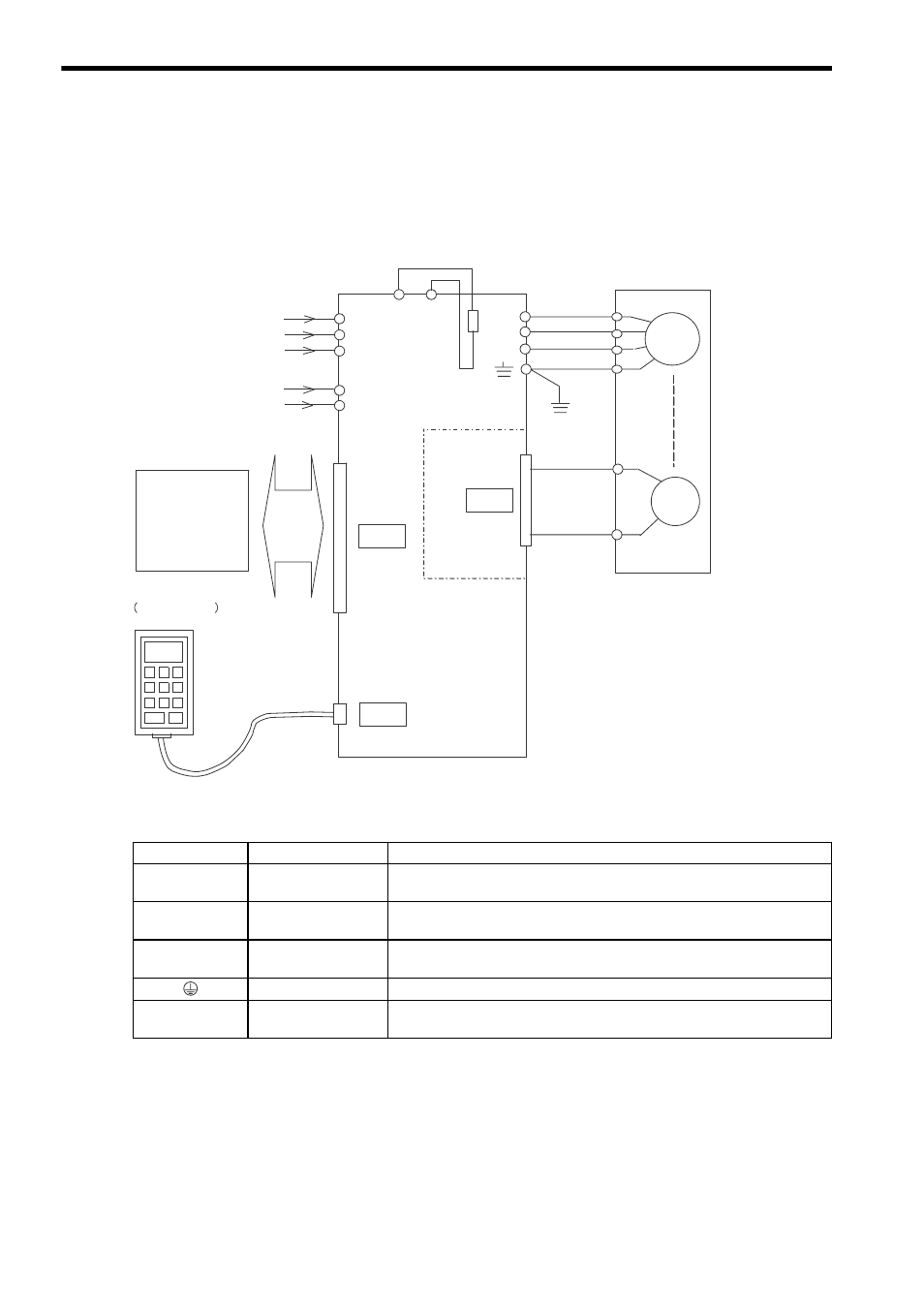
3 Wiring
3.1.1 Connection Diagram
3-2
3.1 Wiring for Re-engineered AC SERVOPACKs
CACR-SRBF1
3.1.1 Connection Diagram
3.1.2 Names and Description of Main Circuit Terminals
R
S
T
r
t
Y3
Y4
U
V
W
Main circuit power supply
Three-phase 200V/220V
50/60 Hz
Control circuit power supply
Single-phase 200V/220V
50/60Hz
M
AC Servomotor
Regenerative
resistor
CN1
CN2
CN3
I/O signals
y
Speed reference
y
PG signal
y
Operation signal
Encoder
Digital operator
JUSP-OP05A
PG
A
B
C
D
Encoder signal
conversion function
built-in
Re-engineered AC SERVOPACK
Terminal Symbol
Name
Description
(R) (S) (T)
Main circuit input
terminals
Three-phase 200 to 230 VAC
+10 to -15 %
, 50/60 Hz
(U) (V) (W)
Servomotor
connection terminals
Connect (U) to the terminal A, (V) to the terminal B, (W) to the terminal C of
Servomotor.
(r) (t)
Control circuit input
terminals
Single-phase 200 to 230 VAC
+10 to -15 %
, 50/60 Hz
Ground terminal
Connect to the power supply ground terminal and the Servomotor D terminal.
(Y3) (Y4)
Regenerative resistor
terminals
Regenerative resistor connection terminals (normally not to be connected
externally.)