U7: coordinated motor monitors, 4 comprehensive parameter list – Yaskawa A1000 User Manual
Page 41
4 Comprehensive Parameter List
YASKAWA TM.A1000SW.064 Electronic Line Shaft with Alignment A1000 Custom Software Supplement
41
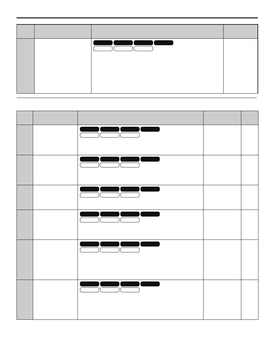
U7: Coordinated Motor Monitors
P4-11
(629)
Repeat Trigger Select
(Repeat Trig Sel)
Selects the method for handling triggers.
0: Last Trigger. If consecutive master triggers (or follower triggers) occur
before a corresponding follower trigger (or master trigger) occurs, the last
master trigger (or follower trigger) is used for alignment.
1: First Trigger. If consecutive master triggers (or follower triggers) occur
before a corresponding follower trigger (or master trigger) occurs, the first
master trigger (or follower trigger) is used for alignment. This option is
identical to F7 functionality.
Default: 0
Range: 0, 1
No.
(Addr.
Hex)
Monitor Name
(Digital Operator
Display)
Description
Analog Output
Scaling
Unit
U7-02
(661)
Master Encoder
Reference
(Master PG Fref)
Displays the frequency of the master encoder before gear ratios and MOP
gains are applied.
Note: Display/Modbus values are limited to -3276.8 to 3276.7
.
Full scale:
Maximum Output
Frequency (E1-04)
0.1 Hz
U7-03
(662)
Follower Reference after
Gear Ratio
(Fref After Gear)
Displays the frequency of the master encoder after the active gear ratio (P1-
03 to P1-08) is applied.
Note: Display/Modbus values are limited to -3276.8 to 3276.7
.
Full scale:
100.00%
0.01%
U7-04
(663)
Gear Ratio Adjustment
(Gear Ratio Adj)
Displays the total gear ratio adjustment (sum of the digital, analog, MOP,
and communication adjustments).
Full scale:
Maximum Output
Frequency (E1-04)
0.1 Hz
U7-05
(664)
Follower Reference after
Gear Ratio Adjustment
(Fref After Adj)
Displays the frequency of the master encoder after the digital, analog, MOP,
and communication gear ratio adjustments are applied.
Note: Display/Modbus values are limited to -3276.8 to 3276.7
.
Full scale:
Maximum Output
Frequency (E1-04)
0.1 Hz
U7-06
(665)
Master Counts/5ms
(Master Cts/5ms)
Displays the number of quadrature encoder counts per 5 ms from the master
drive.
This monitor is representative only and should only be used to confirm that
encoder counts are being received.
Note: ELS modes only.
Full scale:
Counts/5 ms at
Maximum Output
Frequency (E1-04)
cnts
U7-07
(666)
Follower Counts/5ms
(Follower Cts/5ms)
Displays the number of quadrature encoder counts per 5 ms from the
follower drive.
This monitor is representative only and should only be used to confirm that
encoder counts are being received.
Note: ELS modes only.
Full scale:
Counts/5 ms at
Maximum Output
Frequency (E1-04)
cnts
No.
(Addr.
Hex)
Name
(Digital Operator Display)
Description
Values
V/f
OLV/PM
V/f w PG
AOLV/PM
OLV
CLV/PM
CLV
V/f
OLV/PM
V/f w PG
AOLV/PM
OLV
CLV/PM
CLV
OLV/PM
AOLV/PM
CLV/PM
OLV/PM
AOLV/PM
CLV/PM
V/f
OLV/PM
V/f w PG
AOLV/PM
OLV
CLV/PM
CLV
V/f
OLV/PM
V/f w PG
AOLV/PM
OLV
CLV/PM
CLV
OLV/PM
AOLV/PM
CLV/PM
OLV/PM
AOLV/PM
CLV/PM
V/f
OLV/PM
V/f w PG
AOLV/PM
OLV
CLV/PM
CLV
V/f
OLV/PM
V/f w PG
AOLV/PM
OLV
CLV/PM
CLV
OLV/PM
AOLV/PM
CLV/PM
OLV/PM
AOLV/PM
CLV/PM
V/f
OLV/PM
V/f w PG
AOLV/PM
OLV
CLV/PM
CLV
V/f
OLV/PM
V/f w PG
AOLV/PM
OLV
CLV/PM
CLV
OLV/PM
AOLV/PM
CLV/PM
OLV/PM
AOLV/PM
CLV/PM
V/f
OLV/PM
V/f w PG
AOLV/PM
OLV
CLV/PM
CLV
V/f
OLV/PM
V/f w PG
AOLV/PM
OLV
CLV/PM
CLV
OLV/PM
AOLV/PM
CLV/PM
OLV/PM
AOLV/PM
CLV/PM
V/f
OLV/PM
V/f w PG
AOLV/PM
OLV
CLV/PM
CLV
V/f
OLV/PM
V/f w PG
AOLV/PM
OLV
CLV/PM
CLV
OLV/PM
AOLV/PM
CLV/PM
OLV/PM
AOLV/PM
CLV/PM
V/f
OLV/PM
V/f w PG
AOLV/PM
OLV
CLV/PM
CLV
V/f
OLV/PM
V/f w PG
AOLV/PM
OLV
CLV/PM
CLV
OLV/PM
AOLV/PM
CLV/PM
OLV/PM
AOLV/PM
CLV/PM