2 electronic line shaft – Yaskawa A1000 User Manual
Page 13
2 Electronic Line Shaft
YASKAWA TM.A1000SW.064 Electronic Line Shaft with Alignment A1000 Custom Software Supplement
13
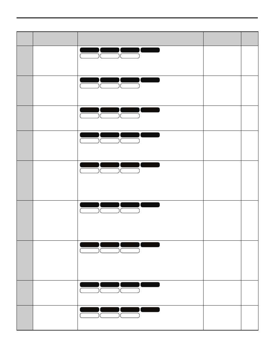
Table 7 Monitors
No.
(Addr.
Hex)
Monitor Name
(Digital Operator
Display)
Description
Analog Output
Scaling
Unit
U7-02
(661)
Master Encoder
Reference
(Master PG Fref)
Displays the frequency of the master encoder before gear ratios and MOP
gains are applied.
Note: Display/Modbus values are limited to -3276.8 to 3276.7
Full scale:
Maximum Output
Frequency (E1-04)
0.1 Hz
U7-03
(662)
Follower Reference after
Gear Ratio
(Fref After Gear)
Displays the frequency of the master encoder after the active gear ratio
(P1-03 to P1-08) is applied.
Note: Display/Modbus values are limited to -3276.8 to 3276.7
Full scale:
Maximum Output
Frequency (E1-04)
0.1 Hz
U7-04
(663)
Gear Ratio Adjustment
(Gear Ratio Adj)
Displays the total gear ratio adjustment (sum of the digital, analog, MOP,
and communication adjustments).
Full scale:
100.00%
0.01%
U7-05
(664)
Follower Reference after
Gear Ratio Adjustment
(Fref After Adj)
Displays the frequency of the master encoder after the digital, analog, MOP,
and communication gear ratio adjustments are applied.
Note: Display/Modbus values are limited to -3276.8 to 3276.7
Full scale:
Maximum Output
Frequency (E1-04)
0.1 Hz
U7-06
(665)
Master Counts/5ms
(Master Cts/5ms)
Displays the number of quadrature encoder counts per 5 ms from the master
drive.
This monitor is representative only and should only be used to confirm that
encoder counts are being received.
Note: ELS modes only.
Full scale:
Counts/5 ms at
Maximum Output
Frequency (E1-04)
cnts
U7-07
(666)
Follower Counts/5ms
(Follower Cts/5ms)
Displays the number of quadrature encoder counts per 5 ms from the
follower drive.
This monitor is representative only and should only be used to confirm that
encoder counts are being received.
Note: ELS modes only.
Full scale:
Counts/5 ms at
Maximum Output
Frequency (E1-04)
cnts
U7-08
(667)
Position Error
(Position Error)
Displays the position error between the master and follower encoders in
quadrature follower encoder counts.
Note: ELS modes only.
Note: Modbus values are limited to -3276.8 to 3276.7. Display values are
limited to -9999 to 99999
Full scale:
Counts/5 ms at
Maximum Output
Frequency (E1-04)
P1-10
U7-09
(668)
Position Regulator P
Output
(Position P Out)
Displays the proportional gain contribution of the position PI regulator.
Note: ELS modes only.
Full scale:
100.00%
0.01%
U7-10
(669)
Position Regulator I
Output
(Position I Out)
Displays the output of the integrator of the position PI regulator.
Note: ELS modes only.
Full scale:
100.00%
0.01%
V/f
OLV/PM
V/f w PG
AOLV/PM
OLV
CLV/PM
CLV
V/f
OLV/PM
V/f w PG
AOLV/PM
OLV
CLV/PM
CLV
OLV/PM
AOLV/PM
CLV/PM
OLV/PM
AOLV/PM
CLV/PM
V/f
OLV/PM
V/f w PG
AOLV/PM
OLV
CLV/PM
CLV
V/f
OLV/PM
V/f w PG
AOLV/PM
OLV
CLV/PM
CLV
OLV/PM
AOLV/PM
CLV/PM
OLV/PM
AOLV/PM
CLV/PM
V/f
OLV/PM
V/f w PG
AOLV/PM
OLV
CLV/PM
CLV
V/f
OLV/PM
V/f w PG
AOLV/PM
OLV
CLV/PM
CLV
OLV/PM
AOLV/PM
CLV/PM
OLV/PM
AOLV/PM
CLV/PM
V/f
OLV/PM
V/f w PG
AOLV/PM
OLV
CLV/PM
CLV
V/f
OLV/PM
V/f w PG
AOLV/PM
OLV
CLV/PM
CLV
OLV/PM
AOLV/PM
CLV/PM
OLV/PM
AOLV/PM
CLV/PM
V/f
OLV/PM
V/f w PG
AOLV/PM
OLV
CLV/PM
CLV
V/f
OLV/PM
V/f w PG
AOLV/PM
OLV
CLV/PM
CLV
OLV/PM
AOLV/PM
CLV/PM
OLV/PM
AOLV/PM
CLV/PM
V/f
OLV/PM
V/f w PG
AOLV/PM
OLV
CLV/PM
CLV
V/f
OLV/PM
V/f w PG
AOLV/PM
OLV
CLV/PM
CLV
OLV/PM
AOLV/PM
CLV/PM
OLV/PM
AOLV/PM
CLV/PM
V/f
OLV/PM
V/f w PG
AOLV/PM
OLV
CLV/PM
CLV
V/f
OLV/PM
V/f w PG
AOLV/PM
OLV
CLV/PM
CLV
OLV/PM
AOLV/PM
CLV/PM
OLV/PM
AOLV/PM
CLV/PM
V/f
OLV/PM
V/f w PG
AOLV/PM
OLV
CLV/PM
CLV
V/f
OLV/PM
V/f w PG
AOLV/PM
OLV
CLV/PM
CLV
OLV/PM
AOLV/PM
CLV/PM
OLV/PM
AOLV/PM
CLV/PM
V/f
OLV/PM
V/f w PG
AOLV/PM
OLV
CLV/PM
CLV
V/f
OLV/PM
V/f w PG
AOLV/PM
OLV
CLV/PM
CLV
OLV/PM
AOLV/PM
CLV/PM
OLV/PM
AOLV/PM
CLV/PM