3 simple automation alignment, Basic concepts and principles, Limitations – Yaskawa A1000 User Manual
Page 21: Simple automation alignment, 3simple automation alignment
3 Simple Automation Alignment
YASKAWA TM.A1000SW.064 Electronic Line Shaft with Alignment A1000 Custom Software Supplement
21
3
Simple Automation Alignment
Basic Concepts and Principles
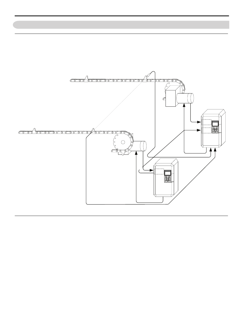
This software adds an automatic alignment feature to the base electronic line shaft software by using two proximity
switches connected to the trigger inputs on the follower drive. One switch indicates the position of the master, and the
other switch indicates the position of the follower. When the alignment feature is activated and the machine is running,
the distance between the trigger switches is measured and then compensated for.
Figure 7
Figure 7 Simple Automation Alignment Diagram
Limitations
• Alignment accuracy is decreased at higher speeds due to latency in the trigger switches and the drive digital inputs and
internal scan rate.
• If the “Clear Position Error” digital input is activated when an alignment is being performed, the drive may experience
a step-change in frequency reference.
• The LED keypad is not officially supported because some alarms and faults may not display properly on the LED
keypad.
M
a
ster
Tr
ig
ger
Switch
Followe
r Trigge
r Switch
Maste
r Mo
tor
Fo
llo
w
er M
o
tor
Mast
er Enco
der
Fo
llo
w
er Enco
der
Gear
Box
Follower
Motor
Master
Motor
A
lig
ne
d
PG-X3
PG-X3
PG-X3
A1000
A1000