Receive pdo configuration and mapping, Transmit pdo configuration and mapping, Fe (hex)) enabled. refer to – Yaskawa 1000 Series Drive Option - CANopen Technical Manual User Manual
Page 29: Change of state filter, Explained in
10 Process Data Objects (PDO)
YASKAWA ELECTRIC SIEP C730600 45B 1000-Series Option SI-S3 Technical Manual
29
◆
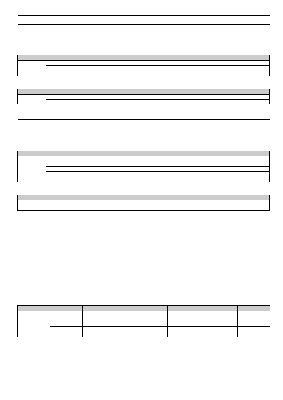
Receive PDO Configuration and Mapping
A receive PDO can be configured using the corresponding 14 (Hex) object, and the mapping can be changed in the 16 (Hex) object that
belongs to the PDO.
■
PDO Configuration
■
PDO Mapping
Note: When changing the PDO mapping, always first set subindex 0 to “0”, then set subindex 1 to subindex n. Then activate the mapping by setting subindex 0 to the number
of mapped objects n.
◆
Transmit PDO Configuration and Mapping
A transmit PDO can be configured by using the corresponding 18 (Hex) object, and the mapping can be changed in the 1A (Hex) object
that belongs to the PDO.
■
PDO Configuration
■
PDO Mapping
Note: When changing the PDO mapping, always first set subindex 0 to “0”, then set subindex 1 to subindex n. Then activate the mapping by setting subindex 0 to the number
of mapped objects n.
■
Transmission Type FE (Hex) for Transmit PDOs
When the transmission type of a TxPDO is set to FE (Hex), the PDO is automatically transmitted whenever the value in one of the mapped objects
changes.
When this transmission type is used for a TxPDO that is mapped to an object with a Change of State filter, the filter can be used to reduce the
amount of data transferred if the object value changes quickly (refer to
Change of State Filter on page 29
). The filter must be set to a value that is
different from FFFF (Hex). If a large filter value is applied, then it can be helpful to also set an event timer for the PDO (18 (Hex), subindex 5).
In this way, the PDO is triggered cyclically even if the change in the value of the linked object does not exceed the filter value. In this way,
variations within the filter can still be seen without having a large number of messages sent.
Note: When a Change of State filter and an event timer are used simultaneously, the PDO will be triggered by whichever one is received first, the timer event or the Change of
State event. If the PDO is triggered by the Change of State event, the event timer will be reset.
■
Change of State Filter
Note: This function is available in option card software 3102 and later.
Some Output objects of the Manufacturer Specific Profile support a Change of State filter. If such an object is mapped to a TxPDOs with
transmission type FE (Change of State), and the filter is set up, a Change of State event is triggered (i.e., the PDO is transmitted) only if the change
in the object value exceeds the filter value. Such objects have the following structure and can be set up as explained below.
Subindex 0: Number of Entries
Contains the number of subindices.
Subindex 1: Object Value
This subindex contains the value of the object (value of the MEMOBUS/Modbus register specified in the subindex 2).
Index (Hex)
Subindex
Content
Default
Access
Data Length
14
0
Largest subindex supported
2
Read Only
1 byte
1
COB-ID used by the RxPDO
see Receive PDO table above
Read/Write
4 byte
2
Transmission type
FE
Read/Write
1 byte
Index (Hex)
Subindex (Hex)
Content
Default
Access
Data Length
16
0
Number of mapped RxPDO’s
see Receive PDO table above
Read/Write
1 byte
1 to 40
Data length, subindex and index of the object to be mapped
see Receive PDO table above
Read/Write
4 byte
Index (Hex)
Subindex
Content
Default
Access
Data Length
18
0
Largest subindex supported
5
Read Only
1 byte
1
COB-ID used by the TxPDO
see TxPDO table above
Read/Write
4 byte
2
Transmission type
depends on PDO
Read/Write
1 byte
3
Inhibit time (Set as a multiple of 100 us)
0
Read/Write
2 byte
5
Event timer (Set as a multiple of 1 ms)
0
Read/Write
2 byte
Index (Hex)
Subindex (Hex)
Content
Default
Access
Data Length
1A
0
Number of mapped PDOs
see transmit PDO table above
Read Only
1 byte
1 to 40
Data length, subindex and index of the object to be mapped
see transmit PDO table above
Read/Write
4 byte
Index (Hex)
<1> Read / Write access when SI-S3 is in the Pre-Operational state, Read only access if the SI-S3 is in the Operational state or if the drive is running.
Subindex
Content
Access
PDO Mapping
Data Length
2101, 2111, 2121,
2131, 2180 to 21E0,
2201
0
Number of entries
Read Only
No
1 byte
1
Object value
Read Only
Possible
2 byte
2
MEMOBUS/Modbus register address for content
Read / Write
No
2 byte
3
Filter value
Read / Write
No
2 byte
4
Filter type
Read / Write
No
2 byte