8 object dictionary – Yaskawa 1000 Series Drive Option - CANopen Technical Manual User Manual
Page 22
8 Object Dictionary
22
YASKAWA ELECTRIC
SIEP C730600 45B 1000-Series Option SI-S3 Technical Manual
■
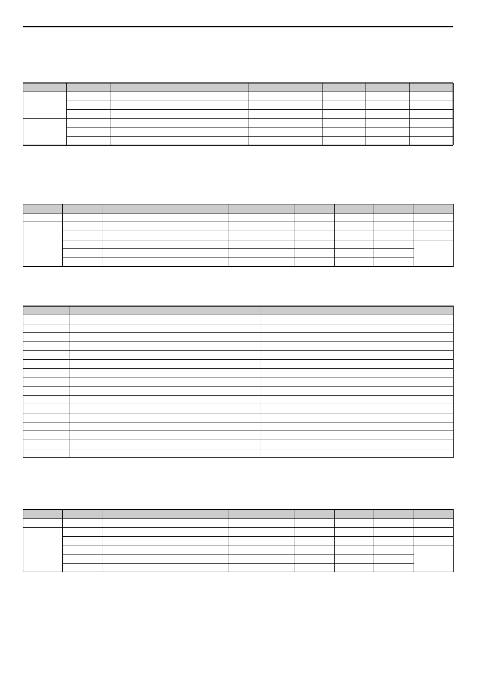
2080 (Hex) to 3100 (Hex) - Freely Configurable Input Objects
The content of these objects can be freely selected by linking them to drive MEMOBUS/Modbus registers. Refer to
for details.
■
2100 (Hex) / 2101 (Hex) - Drive Status
These objects can be used to monitor the drive status. The value in object 2100 (Hex) is not filtered. For the value in object 2101 (Hex) a Change of
State filter can be set up as explained in
Change of State Filter on page 29
Table 7 Drive Status
■
2110 (Hex) / 2111 (Hex) - Output Frequency
These objects can be used to monitor the output frequency. The value in object 2110 (Hex) is not filtered. For the value in object 2111 (Hex) a
Change of State filter can be set up as explained in
Change of State Filter on page 29
. The units used for the monitor value are determined by drive
parameter o1-03.
Index (Hex)
<1> Available in option card software version 3102 and later.
<2> Read / Write access when SI-S3 is in the Pre-Operational state and read-only access if the SI-S3 is in the Operational state or if the drive is running.
Subindex
Content
Default
Access
PDO Mapping
Data Length
2080
0
Number of entries
2
Read Only
No
1 byte
1
Value
-
Read / Write
Possible
4 byte
2
MEMOBUS/Modbus register address for content 1 and 2
FFFF (Hex) / FFFF (Hex)
Read / Write
No
4 byte
2090 to 20C0,
3000, and
3100
0
Number of entries
2
Read Only
No
1 byte
1
Value
-
Read / Write
Possible
2 byte
2
MEMOBUS/Modbus register address for content
FFFF (Hex)
Read / Write
No
2 byte
Index (Hex)
<1> Available in option card software version 3102 and later.
<2> For details of the drive status, refer to
<3> Read / Write access when SI-S3 is in the Pre-Operational state, Read only access if the SI-S3 is in the Operational state or if the drive is running.
Subindex
Content
Default
Access
PDO Mapping Data Length Update Cycle
2100
0
Drive Status
-
Read Only
Possible
2 byte
2 ms
2101
0
Number of entries
4
Read Only
No
1 byte
-
1
Drive Status
-
Read Only
Possible
2 byte
2 ms
2
MEMOBUS/Modbus register address for content
00FC (Hex)
Read Only
No
2 byte
-
3
Filter value
0
Read / Write
No
2 byte
4
Value filter type
1 (Bitmask)
Read / Write
No
2 byte
Bit No. (Hex)
Function
Description
0
During Run
1: During Run 0: During Stop
1
During Zero Speed
1: During Zero Speed
2
Reverse Running
1: During Reverse Running 0: During Forward Running
3
During Fault Reset Signal Input
1: During Fault Reset Signal Input
4
During Speed Agree
1: During Speed Agree
5
During Drive Ready
1: During Drive Ready 0: Not Ready
6
During Alarm
1: During Alarm
7
During Fault
1: During Fault
8
During Operation Error
1: During Operation Error
9
During Momentary Power Loss
1: During Momentary Power Loss 0: During Power Loss
A NetCtrl
Status
1:
NetCtrl
B
Digital Output 1 Status (function set in drive parameter H2-01)
1: ON 0: OFF
C
Digital Output 2 Status (function set in drive parameter H2-02)
1: ON 0: OFF
D
Digital Output 3 Status (function set in drive parameter H2-03)
1: ON 0: OFF
E
Motor 2 Selected
1: Motor 2 Selected
F
Zero-Servo End
1: Zero-Servo End
Index (Hex)
<1> Available in option card software version 3102 and later.
<2> Read / Write access when SI-S3 is in the Pre-Operational state, Read only access if the SI-S3 is in the Operational state or if the drive is running.
Subindex
Content
Default
Access
PDO Mapping Data Length Update Cycle
2110
0
Output Frequency
-
Read Only
Possible
2 byte
2 ms
2111
0
Number of entries
4
Read Only
No
1 byte
-
1
Output Frequency
-
Read Only
Possible
2 byte
2 ms
2
MEMOBUS/Modbus register address for content
0041 (Hex)
Read Only
No
2 byte
-
3
Filter value
FFFF (Hex)
Read / Write
No
2 byte
4
Value filter type
0 (Analog)
Read / Write
No
2 byte