Drives and motion profile objects (dsp 402), 8 object dictionary – Yaskawa 1000 Series Drive Option - CANopen Technical Manual User Manual
Page 24
8 Object Dictionary
24
YASKAWA ELECTRIC
SIEP C730600 45B 1000-Series Option SI-S3 Technical Manual
■
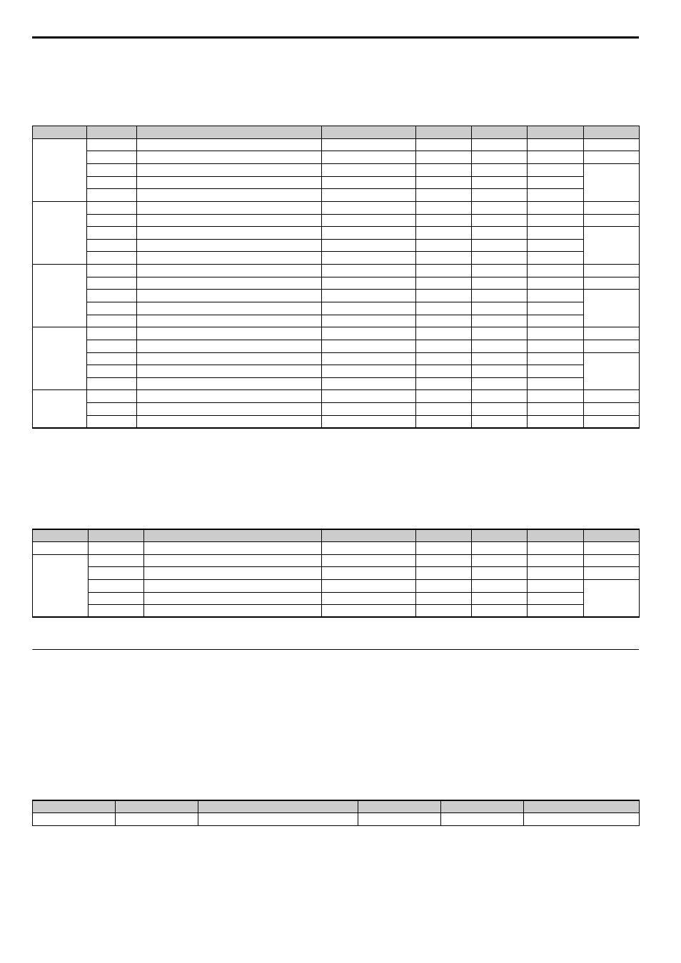
2180 (Hex) to 21F0 (Hex) - Freely Configurable Output Objects
Note: These objects are available in option card software version 3102 and later.
The content of these objects can be freely selected by linking them to drive MEMOBUS/Modbus registers. For 2 byte objects a Change of State
filter can be applied. Refer to
Change of State Filter on page 29
for details.
■
2200 (Hex) / 2201 (Hex) - Motor Speed
These objects can be used to monitor the motor speed. The value in object 2200 (Hex) is not filtered. For the value in object 2201 (Hex), a Change
of State filter can be set up as explained in
Change of State Filter on page 29
.
The availability of the object content depends on the drive control mode. If the selected control mode does not support this monitor (equal to drive
monitor U1-05), the object value will be 0. Refer to the drive technical manual for details.
◆
Drives and Motion Profile Objects (DSP 402)
The drive supports Drive and Motion Profile DSP 402 Velocity Mode. Before using Velocity Mode, objects for following parameters must be set up
in the drive:
• The number of motor poles must be set to E2-04.
• The frequency reference and output frequency display unit must be set to r/min by setting parameter o1-03 = 2.
If these settings are incorrect, the Velocity Mode objects may be unusable, or the drive might not operate as expected.
Note: Drive and Motion Control (DSP 402) cannot be set or referenced unless o1-03 = 2.
■
6040 (Hex) - Controlword
This object sets the device to different states.
Index (Hex)
<1> Read / Write access when SI-S3 is in the Pre-Operational state, Read only access if the SI-S3 is in the Operational state or if the drive is running.
Subindex
Content
Default
Access
PDO Mapping Data Length Update Cycle
2180
0
Number of entries
4
Read Only
No
1 byte
-
1
Value
Input Terminal Status
Read Only
Possible
2 byte
8 ms
2
MEMOBUS/Modbus register address for content
0049 (Hex)
Read / Write
No
2 byte
-
3
Filter value
0
Read / Write
No
2 byte
4
Value filter type
1 (Bitmask)
Read / Write
No
2 byte
2190
0
Number of Entries
4
Read Only
No
1 byte
-
1
Value
Analog Input A1 Monitor
Read Only
Possible
2 byte
8 ms
2
MEMOBUS/Modbus register address for content
004E (Hex)
Read / Write
No
2 byte
-
3
Filter value
FFFF (Hex)
Read / Write
No
2 byte
4
Value filter type
0 (Analog)
Read / Write
No
2 byte
21A0
0
Number of entries
4
Read Only
No
1 byte
-
1
Value
-
Read Only
Possible
2 byte
8 ms
2
MEMOBUS/Modbus register address for content
FFFF (Hex)
Read / Write
No
2 byte
-
3
Filter value
FFFF (Hex)
Read / Write
No
2 byte
4
Value filter type
0 (Analog)
Read / Write
No
2 byte
21B0 to 21E0
0
Number of entries
4
Read Only
No
1 byte
-
1
Value
-
Read Only
Possible
2 byte
2 ms
2
MEMOBUS/Modbus register address for content
FFFF (Hex)
Read / Write
No
2 byte
-
3
Filter value
FFFF (Hex)
Read / Write
No
2 byte
4
Value filter type
0 (Analog)
Read / Write
No
2byte
21F0
0
Number of entries
2
Read Only
No
1 byte
-
1
Value
-
Read Only
Possible
4 byte
8 ms
2
MEMOBUS/Modbus register address for content 1 and 2 FFFF (Hex)/FFFF (Hex) Read / Write
No
4 byte
-
Index (Hex)
<1> Available in option card software version 3102 and later.
<2> Read / Write access when SI-S3 is in the Pre-Operational state, Read only access if the SI-S3 is in the Operational state or if the drive is running.
Subindex
Content
Default
Access
PDO Mapping Data Length Update Cycle
2200
0
Motor Speed
-
Read Only
Possible
2 byte
2 ms
2201
0
Number of Entries
4
Read Only
No
1 byte
-
1
Motor Speed
-
Read Only
Possible
2 byte
2 ms
2
MEMOBUS/Modbus register address for content
0044 (Hex)
Read Only
No
2 byte
-
3
Filter value
FFFF (Hex)
Read / Write
No
2 byte
4
Value filter type
0 (Analog)
Read / Write
No
2 byte
Index (Hex)
Subindex
Content
Access
PDO Mapping
Value Range
6040
0
Controlword
Read / Write
Possible
0...65535