Communication profile objects (ds 301), 8 object dictionary, Drives and motion profile objects (dsp 402) – Yaskawa 1000 Series Drive Option - CANopen Technical Manual User Manual
Page 16
8 Object Dictionary
16
YASKAWA ELECTRIC
SIEP C730600 45B 1000-Series Option SI-S3 Technical Manual
■
Drives and Motion Profile Objects (DSP 402)
The drive supports the Drive and Motion Profile DSP 402 Velocity Mode. Before using the Velocity Mode objects the following parameters have to
be set up in the drive:
• The motor pole number must be set up in E2-04.
• The frequency reference and output frequency display unit has to be set to min
-1
by setting parameter o1-03 = 2.
If these settings are not done properly, the Velocity Mode objects cannot be used or deliver wrong data.
◆
Communication Profile Objects (DS 301)
■
1000 (Hex) - Device Type
This object describes the type of device and its functionality. It is composed of a first 16 bit field that describes the device profile used and a second
16 bit field that gives additional information regarding optional functionality.
■
1001 (Hex) - Error Register
This register shows the fault status of the device. If any errors occurs in the device bit 0 (generic error) is set to one.
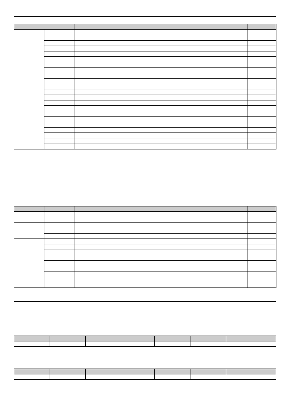
Output
2100
Drive Status
2101
Drive Status (Change of State filter support)
2110
Output Frequency
2111
Output Frequency (Change of State filter support)
2120
Output Current
2121
Output Current (Change of State filter support)
2130
Output Torque
2131
Output Torque (Change of State filter support)
2140
MEMOBUS/Modbus Read Command Response
2150
MEMOBUS/Modbus Write Command Response
2155
PDO Parameter Write Response
2160
MEMOBUS/Modbus Not Limited Enter Command Response
2180
Freely selectable (default: Input terminal status)
2190
Freely selectable (default: Analog input 1 monitor)
21A0
Freely selectable (default: none)
21B0
Freely selectable (default: none)
21C0
Freely selectable (default: none)
21D0
Freely selectable (default: none)
21E0
Freely selectable (default: none)
Freely selectable (default: none)
2200
Motor Speed
2201
Motor Speed (Change of State filter support)
<1> Available in option card software version 3102 and later.
<2> Units for motor speed are determined by o1-03. If the control mode for the drive is set to V/f control (A1-02=0) and V/f control with simple PG feedback is disabled (H6-01
≠3), then the
motor speed will be 0.
Object Type
<1> YASKAWA specifies this object as the drive digital output monitor. (Input from the network)
<2> YASKAWA specifies this object as the drive digital inputs. (Output to the network)
Index (Hex)
Name
Page
Common Entries
60FD
Digital Inputs
60FE
Digital Outputs
Device Control
6040
Controlword
6041
Statusword
6061
Modes of operation display
Velocity Mode
6042
vl target velocity
6043
vl velocity demand
6044
vl control effort
6046
vl velocity min max amount
6048
vl velocity acceleration
6049
vl velocity deceleration
604A
vl velocity quick stop
604C
vl dimension factor
604D
vl pole number
Index (Hex)
Subindex
Content
Access
PDO Mapping
Value Range
1000
–
Device type
Read Only
No
Unsigned 32
Index (Hex)
Subindex
Content
Access
PDO Mapping
Value Range
1001
–
Error register
Read Only
Possible
Unsigned 8
Index (Hex)
Content
Page