HEIDENHAIN ND 231 B v.2 User Manual
Page 38
38
Pin layout RS-232-C/V.24 (X31)
Pin
Signal
Assignment
1
CHASSIS GND
Chassis ground
2
TXD
Transmitted data
3
RXD
Received data
4
RTS
Request to send
5
CTS
Clear to send
6
DSR
Data set ready
7
SIGN. GND
Signal ground
8 to 19
–
Not assigned
20
DTR
Data terminal ready
21 to 25
–
Not assigned
Levels for TXD and RXD
Logic level
Voltage level
Active
– 3 V to – 15 V
Not active
+ 3 V to +15 V
Levels for RTS, CTS, DSR and DTR
Logic level
Voltage level
Active
+ 3 V to + 15 V
Not active
– 3 V to – 15 V
RS-232-C/V.24 Data Interface (X31)
Data format and control characters
Data format
1 start bit
7 data bits
Even parity bit
2 stop bits
Control characters
Call measured value: STX (Ctrl B)
Interrupt DC3 (Ctrl S)
Continue DC1 (Ctrl Q)
Interrogate error message: ENQ (Ctrl E)
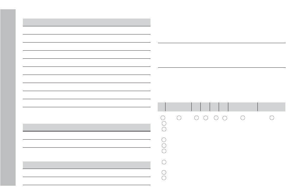
Example: Data sequence during measured value output
Measured value = – 5.23 mm
The measured value is within the sorting limits ( = ) and the
selected display is X1.
Measured value output
- 5 . 2 3 = 1 < C R > < L F >
1
2
3
4
5
6
7
8
1
Algebraic sign
2
Numerical value with decimal point (10 characters on
the whole, leading zeros are transferred as blanks.)
3
Blank space
4
Unit: Blank space = mm; " = inch; ? = fault
5
Sorting status (<, >, =; ? if P18 > P19)
or blank space
6
Axis designation (1 = X1, 2 = X2, A = X1 + X2,
S = X1 – X2)
7
CR (carriage return)
8
LF (line feed)