Grass Valley SME-1901 v.1.20 User Manual
Page 14
GUIDE TO INSTALLATION AND OPERATION
10 | SME-1901 / 1911
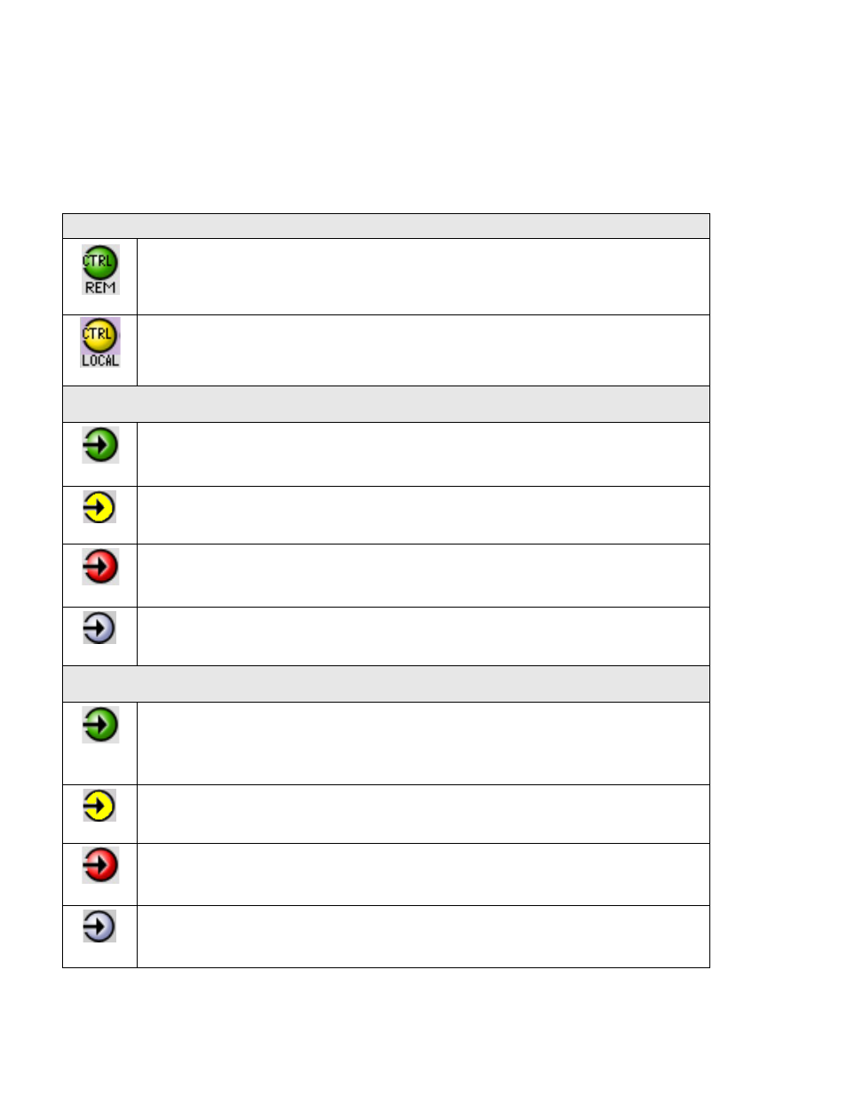
The table below describes the various status icons that can appear, and how they are to be interpreted.
• In cases where there is more than one possible interpretation, read the error message in the iControl window to
see which applies.
Table – iControl Status Icon interpretation
Icon #1 – Manual Card Configuration
(green)
Remote card control activated. The iControl interface can be used to operate the card
(yellow)
Local card control active, The card is being controlled using the Densité frame control
panel, as described in section 4. Any changes made using the iControl interface will have
no effect on the card.
Icon #2 – Electrical Input (IN 1) Status
(green)
Carrier detected and locked
• Mouse over the icon to see format details.
(yellow)
Carrier detected
(red)
Signal absent
No rear
(gray)
Optical input selected.
Icon #3 – Optical Input (IN 2) Status
(green)
Carrier detected and locked.
• Mouse over the icon to see format details
(yellow)
Carrier detected
(red)
Signal absent
No rear
(gray)
Electrical input selected.