Midplane, Disk modules, Midplane disk modules – Grass Valley K2 Level 2 RAID Oct.10 2006 User Manual
Page 20: Chapter 1 about the k2 level 2 raid storage
20
Level 2 RAID Instruction Manual
September 8, 2006
Chapter 1 About the K2 Level 2 RAID storage
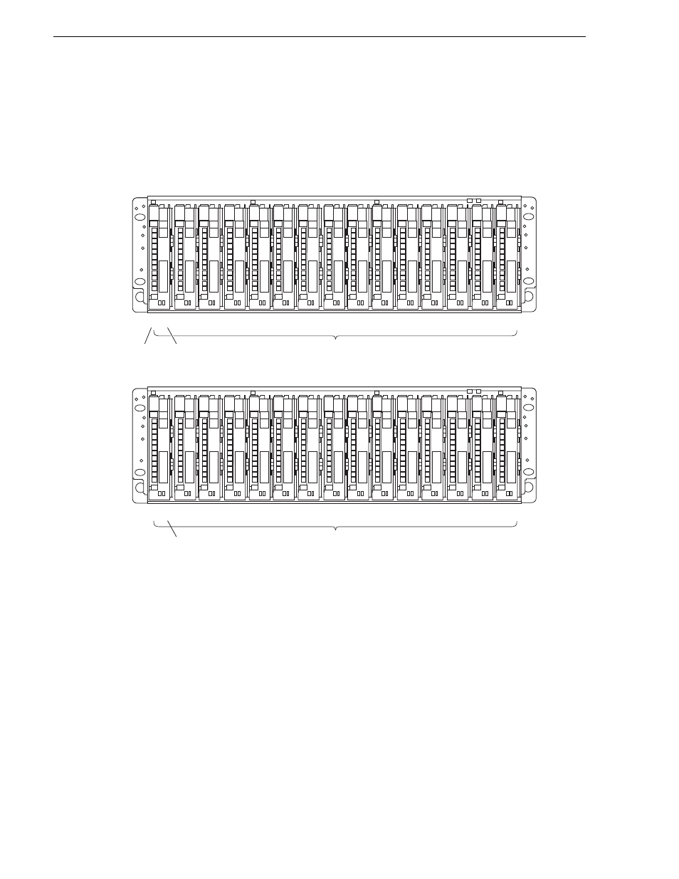
The following diagram shows how disk modules are identified based on the chassis
address and physical location. The chassis with an address set to 0 contains drives
from 0 to 14; the expansion chassis with an address set to 1 contains drives from 16
to 30. There is no drive 15 in the numbering sequence.
An operating primary RAID chassis must have, at a minimum, the first three physical
drives (0 - 2) installed, as the RAID configuration information is written to these
drives. Microcode is also written to these disks when RAID controller microcode is
loaded.
Midplane
The midplane distributes power and signals to all the chassis components. All FRUs
plug directly into midplane connectors.
Disk modules
Each disk module consists of a Fibre Channel disk drive in a carrier assembly. If a
disk drive fails, and needs replacing, you can do so while the RAID Storage Chassis
is powered up. Replacement disk drives begin rebuilding immediately after being
installed. (See
“Removing and installing disk modules” on page 47
.)
0
00
0
01
0
02
0
03
0
04
Disk Modules
Primary chassis
Expansion chassis
0
05
0
06
0
07
0
08
0
09
0
10
0
11
0
12
0
13
0
14
Disk
ID
Chassis
Address
Expansion chassis
starts with disk 16.
There is no disk 15.
1
16
1
17
1
18
1
19
1
20
Disk Modules
1
21
1
22
1
23
1
24
1
25
1
26
1
27
1
28
1
29
1
30