Interpreting power supply status leds, Moving disk modules – Grass Valley K2 10G RAID User Manual
Page 60
18 November 2010
K2 10G RAID Storage Instruction Manual
60
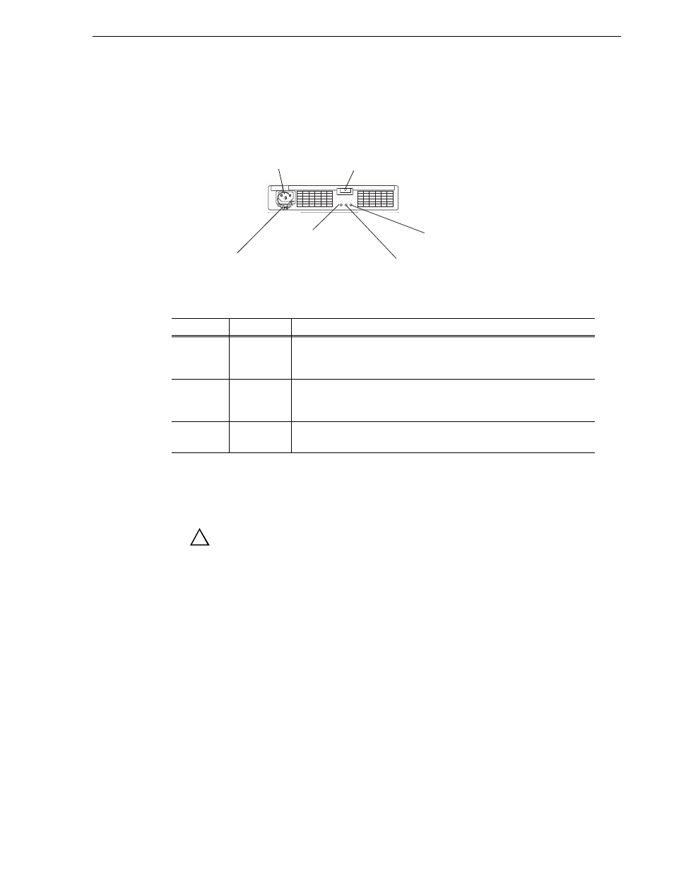
Interpreting power supply status LEDs
Interpreting power supply status LEDs
Use the following illustration and table to identify and interpret power supply LEDs
.
Moving disk modules
CAUTION: Once bound and added to file system, don’t re-arrange the
disk modules and change the discovery order. You can destroy the
media file system beyond recovery if you move a disk module to a
different slot. The service person can move a disk module when you
don’t care about losing the media in the media file system and under
the following cautions:
• The disk module must be unbound.
• Moving a drive module that is part of a LUN to another slot makes all information
on the LUN inaccessible.
• You must remove and install the disk module while the storage system is powered
up.
• In a location that does not mount a disk drive, mount a dummy carrier. It is
necessary for the cooling of the unit.
A disk module must be inserted all the way or removed entirely. Do not leave a disk
module partially removed except for periods when you are allowing it to spin down.
When replacing multiple disks, observe the following:
LED
Action
Meaning
Power
Good
(green)
On
AC power is supplied to the chassis.
Power
Fault
(orange)
On
Fault in power supply (excluding the fan) or battery backup unit. This
LED works when AC power of either PS0 or PS1 is supplied.
Fan Fault
(orange)
On
Fault in the fan. This LED works when AC power of either PS0 or PS1 is
supplied.
Power plug (1)
Ejector (5)
Power cable clamp (6)
Power Good LED (2) Fan Fault LED (4)
Power Fault LED (3)
!