Interpreting controller status leds, Raid controller – Grass Valley K2 10G RAID User Manual
Page 56
18 November 2010
K2 10G RAID Storage Instruction Manual
56
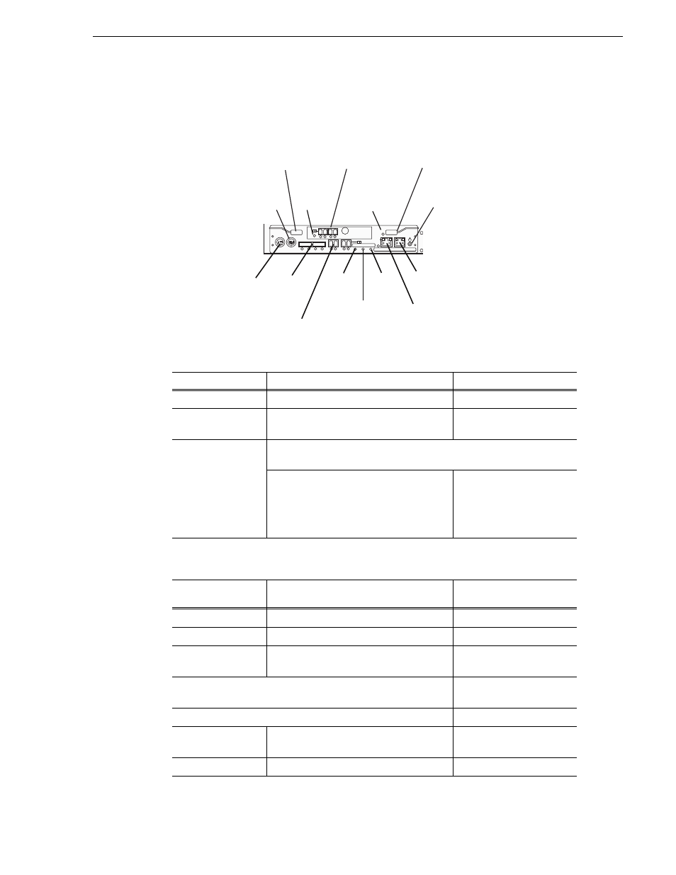
Interpreting controller status LEDs
Interpreting controller status LEDs
Use the following illustration and table to identify and interpret controller LEDs.
Indicator
Description
Power button (1)
Turns power on and off
MNT connector (2)
Connects the controller to a maintenance
PC
LAN connector(3)
Connects the controller to a Storage Manager or a LAN for SNMP.
On the left is the LINK LED (green), which
indicates that a LAN is physically
connected.
On the right is the Active
LED (orange), which
illuminates during a TCP
protocol connection from a
host.
Ready LED (4)
(green)
Fault LED (5)
(orange)
Meaning
Blinking
Off
Normal operation
On
Off
Starting
Blinking (2 times/
second)
Off
Shutdown sequence in
progress
Blinking asynchronously
Online/automatic download
sequence in progress
Blinking synchronously
In download mode
Blinking
On
Disk interface is
unavailable
On
On
Occurrence of fault
BBU IN
MODEM
FLT/LNK
FLT
A/L
BACKUP
A/L
UPS
LNK/ACT
FLT
HP
3 2
RDY
LAN
BAT
MNT
ACS
MC
DP1
DP0
HP
1 0
BBU IN
MODEM
FLT/LNK
HPE
FLT
A/L
BACKUP
ACT/LNK
LNK/ACT
FLT
HP
5 4 3 2
RDY
LAN
BA
ACS
MC
DP1
DP0
HP
1 0
Modem
Connector
(10)
Ejector (11)
HPE
Fault LED
(12)
HPE (13)
BBU
Fault LED
(14)
Ejector (11)
Power
Button (1)
Extended BBU
Connector
(9)
SAS
Connector
(8)
HP Connector
(7)
LAN
Connector (3)
Fault
LED (5)
Ready
LED (4)
Backup
LED (6)
MNT
Connector (2)
RAID
Controller