Genlock submodule installation – Grass Valley 8985FS v.1.2.0 User Manual
Page 15
8985FSP/FS/PRC — Instruction Manual
15
Installation
Genlock Submodule Installation
The Genlock submodule will ship separately and must be mounted on the
8985FSP/FS module. Refer to
8985FSP/FS Module Placement For Genlock
and the 8900GEN-SM GeckoFlex Genlock Submodule Instal-
lation Manual available online for frame timing configuration information
and determining the position of the module(s) in the frame.
To install a submodule onto the main circuit board, follow the instructions
below:
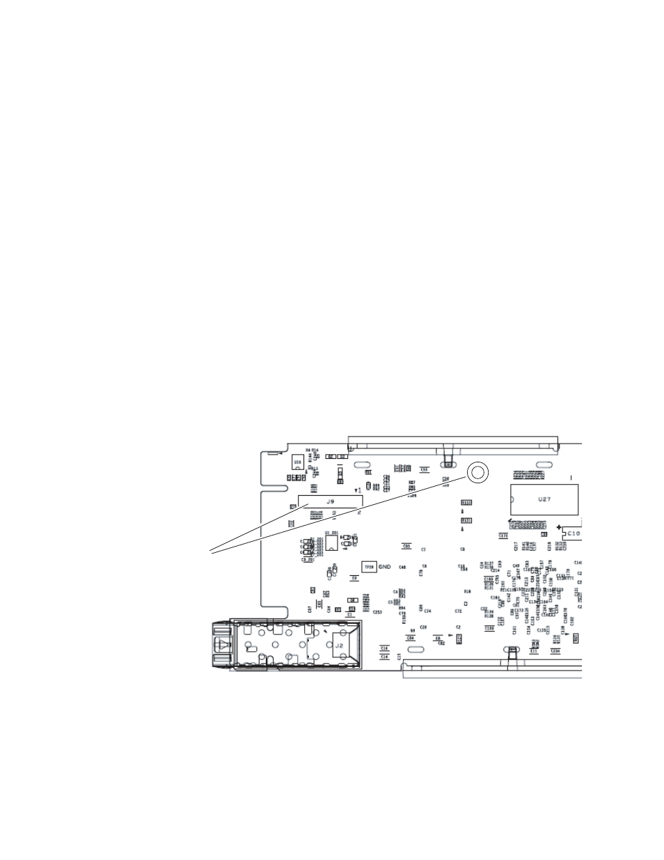
1.
Locate the Genlock connector J9, on the back side of the 8985FSP circuit
board (
2.
Line up the connector J1, on the submodule, with J9 on the back side of
front module and snap the submodule into place making sure the holes
in each circuit board line up.
3.
To hold the submodule in place, attach the captive screw provided from
the top of the front module to the standoff on the front module circuit
board.
4.
To remove the submodule, loosen the captive screw and carefully pull
the submodule off the circuit board.
Figure 3. Install Genlock Submodule on Back of 8985FSP Circuit Board
8431_05
Install Genlock submodule
on back of circuit board.
Center submodule connector J1
over front module connector J9
and snap in place. From top side
of module, tighten the captive
screw to the standoff on the
circuit board.