Grass Valley 2000NET v3.1 User Manual
Page 12
12
2000NET Instruction Manual
Installation
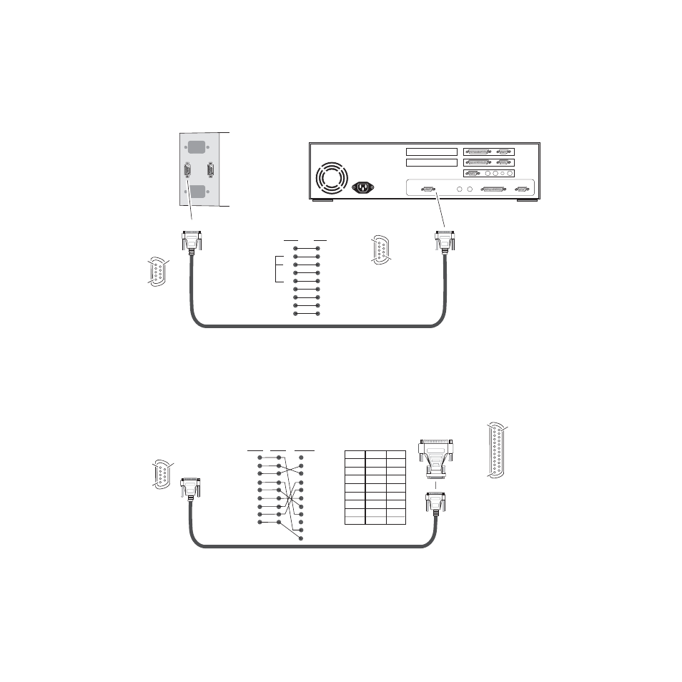
The male end connects to J101 on the 2000T3 frame (see
female end connects to either Comm 1 or Comm 2 on the PC, depending
upon the configuration of the computer’s I/O ports.
Figure 6. RS-232 to Initialization PC Cable and Pinout
If the PC uses a 25-pin RS-232 connector, use a cable adapter as shown in
.
Figure 7. DB-9 Cable and DB-25 Cable Adaptor Pinout
2000T3 Frame
DB-9
Female
DB-9
Female
Pinout
DB-9
Male
Comm 1 or
Comm 2 port
J101
RS-232
PC running Hyperterm Terminal Emulation
8046 -09r1
Comm. Parameters: 9600 baud, 8 bits, parity-none, 1 stop, flow-none
Only pins
2,3, & 5
are required
Pin
Pin
1
2
3
4
5
6
7
8
9
1
2
3
4
5
6
7
8
9
Pin 1
Pin 5
Pin 9
DB-9
Male
Pinout
Pin 5
Pin 1
Pin 9
1
2
3
4
5
6
7
8
9
1
2
3
4
5
6
7
8
9
8
3
2
20
7
6
4
5
22
8046 -19r2
25-pin
25-pin
9-pin
9-pin
9-pin
Note: Only Tx, Rx and pin 5 (9-pin) to pin 7 (25-pin) are required.
1
2 Tx
3 Rx
4
5
6
7
8
9
20
22
1
Tx 2
Rx 3
4
5
6
7
8
9
9-pin
DB-25
Female
DB-25
Female
Pinout
DB-9
Male
Pinout
DB-9
Female
Pin 5
Pin 1
Pin 9
Pin 1
Pin 13
Pin 14