Configuration example, Network requirements, Configuration procedure – H3C Technologies H3C S7500E Series Switches User Manual
Page 200
15-43
tunnel. It is not allowed to set up a static route whose destination address is in the subnet of the
tunnel interface.
Configuration Example
Network requirements
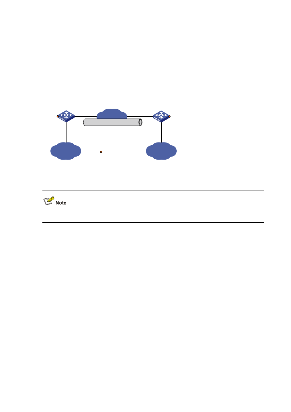
Two IPv4 subnets Group 1 and Group 2 are interconnected through a GRE tunnel over the IPv6
network between Switch A and Switch B.
Figure 15-15 Network diagram for a GRE over IPv6 tunnel
Vlan-int100
10.1.3.1/24
IPv4
Group 2
IPv4
Group 1
Vlan-int100
10.1.1.1/24
Tunnel0
10.1.2.1/24
Vlan-int101
2002::1:1/64
Vlan-int101
2002::2:1/64
IPv6 network
GRE tunnel
Tunnel0
10.1.2.2/24
Switch A
Switch B
Service loopback port
GE2/0/3
GE2/0/3
Configuration procedure
Before the configuration, make sure that Switch A and Switch B are reachable to each other.
1) Configure Switch A
# Enable IPv6.
[SwitchA] ipv6
# Configure interface VLAN-interface 100.
[SwitchA] interface vlan-interface 100
[SwitchA-Vlan-interface100] ip address 10.1.1.1 255.255.255.0
[SwitchA-Vlan-interface100] quit
# Configure interface VLAN-interface 101, the physical interface of the tunnel.
[SwitchA] interface vlan-interface 101
[SwitchA-Vlan-interface101] ipv6 address 2002::1:1 64
[SwitchA-Vlan-interface101] quit
# Create an interface named Tunnel 0.
[SwitchA] interface tunnel 0
# Configure an IPv4 address for interface Tunnel 0.
[SwitchA-Tunnel0] ip address 10.1.2.1 255.255.255.0
# Configure the tunnel encapsulation mode.
[SwitchA-Tunnel0] tunnel-protocol gre ipv6