Configuration example, Network requirements, Configuration procedure – H3C Technologies H3C S7500E Series Switches User Manual
Page 196
15-39
To do…
Use the command…
Remarks
Configure a route through the
tunnel
Refer to the Layer 3 - IP Routing
Configuration Guide.
Optional
Each end of the tunnel must have
a route (static or dynamic) through
the tunnel to the other end.
Note that:
z
The source address and destination address of a tunnel uniquely identify a path. They must be
configured at both ends of the tunnel and the source address at one end must be the destination
address at the other end and vice versa.
z
Tunnel interfaces using the same encapsulation protocol must have different source addresses
and destination addresses.
z
If you configure a source interface for a tunnel interface, the tunnel interface takes the primary IP
address of the source interface as its source address.
z
When configuring a route through the tunnel, you can configure a static route, using the address of
the network segment that the original packet is destined for as its destination address and the
address of the peer tunnel interface as its next hop. Or, you can enable a dynamic routing protocol
on both the tunnel interface and the router interface connecting the private network.
Configuration Example
Network requirements
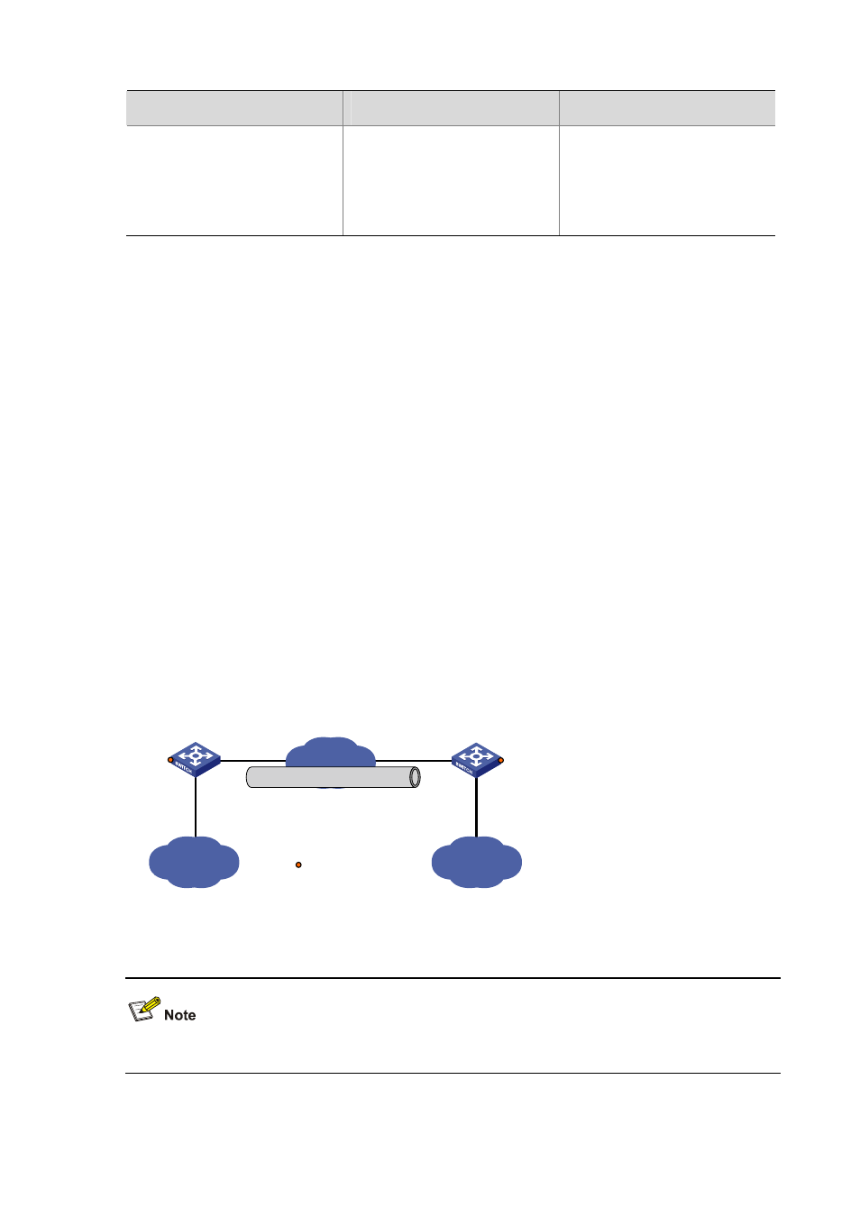
Switch A and Switch B are interconnected through the Internet. Two private IPv4 subnets Group 1 and
Group 2 are interconnected through a GRE tunnel between the two switches.
Figure 15-14 Network diagram for a GRE over IPv4 tunnel
IPv4
Group 2
IPv4
Group 1
Vlan-int100
10.1.1.1/24
Vlan-int100
10.1.3.1/24
Tunnel1
10.1.2.1/24
Vlan-int101
1.1.1.1/24
Vlan-int101
2.2.2.2/24
IPv4 network
GRE tunnel
Tunnel1
10.1.2.2/24
Switch A
Switch B
Service loopback port
GE2/0/3
GE2/0/3
Configuration procedure
Before the configuration, make sure that Switch A and Switch B are reachable to each other.
1) Configure Switch A