Configuration example, Network requirements, Configuration procedure – H3C Technologies H3C S7500E Series Switches User Manual
Page 182
15-25
Configuration Example
Network requirements
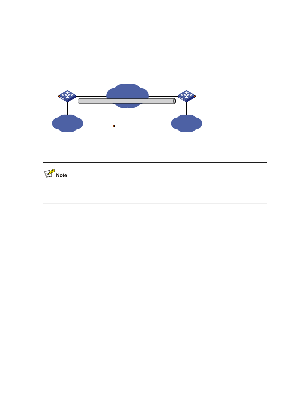
The two subnets Group 1 and Group 2 running IPv4 are interconnected via an IPv4 over IPv4 tunnel
between Switch A and Switch B.
Figure 15-11 Network diagram for an IPv4 over IPv4 tunnel
GE2/0/3
GE2/0/3
Vlan-int101
2.1.1.1/24
Vlan-int100
10.1.3.1/24
Vlan-int100
10.1.1.1/24
Switch A
IPv4 netwok
IPv4
Group 1
Tunnel1
10.1.2.1/24
Vlan-int101
3.1.1.1/24
Tunnel2
10.1.2.2/24
IPv4
Group 2
Switch B
Service loopback port
Configuration procedure
Make sure that Switch A and Switch B have the corresponding VLAN interfaces created and are
reachable to each other.
z
Configuration on Switch A
# Configure an IPv4 address for VLAN-interface 100.
[SwitchA] interface vlan-interface 100
[SwitchA-Vlan-interface100] ip address 10.1.1.1 255.255.255.0
[SwitchA-Vlan-interface100] quit
# Configure an IPv4 address for VLAN-interface 101.
[SwitchA] interface vlan-interface 101
[SwitchA-Vlan-interface101] ip address 2.1.1.1 255.255.255.0
[SwitchA-Vlan-interface101] quit
# Create the interface tunnel 1.
[SwitchA] interface tunnel 1
# Configure an IPv4 address for the interface tunnel 1.
[SwitchA-Tunnel1] ip address 10.1.2.1 255.255.255.0
# Configure the tunnel encapsulation mode.
[SwitchA-Tunnel1] tunnel-protocol ipv4-ipv4
# Configure a source address for the interface tunnel 1 (IP address of VLAN-interface 101).
[SwitchA-Tunnel1] source 2.1.1.1
# Configure a destination address for the interface tunnel 1 (IP address of VLAN-interface 101 of
Switch B).
[SwitchA-Tunnel1] destination 3.1.1.1
[SwitchA-Tunnel1] quit