Planning irf topology and connections, Installing irf member switches – H3C Technologies H3C S9800 Series Switches User Manual
Page 55
47
An IRF fabric has only one master switch. You configure and manage all member switches in the IRF
fabric at the CLI of the master. IRF member switches will automatically elect a master. You can affect the
election result by assigning a high member priority to the intended master switch. For more information
about master election, see H3C S9800 Switch Series IRF Configuration Guide.
Prepare an IRF member ID assignment scheme. An IRF fabric uses member IDs to uniquely identify and
manage its members, and you must assign each IRF member switch a unique member ID.
Planning IRF topology and connections
Connect the IRF member switches through IRF ports, the logical interfaces for the connections between
IRF member switches. Each IRF member switch has two IRF ports: IRF-port 1 and IRF-port 2. To use an IRF
port, you must bind a minimum of one physical port to it.
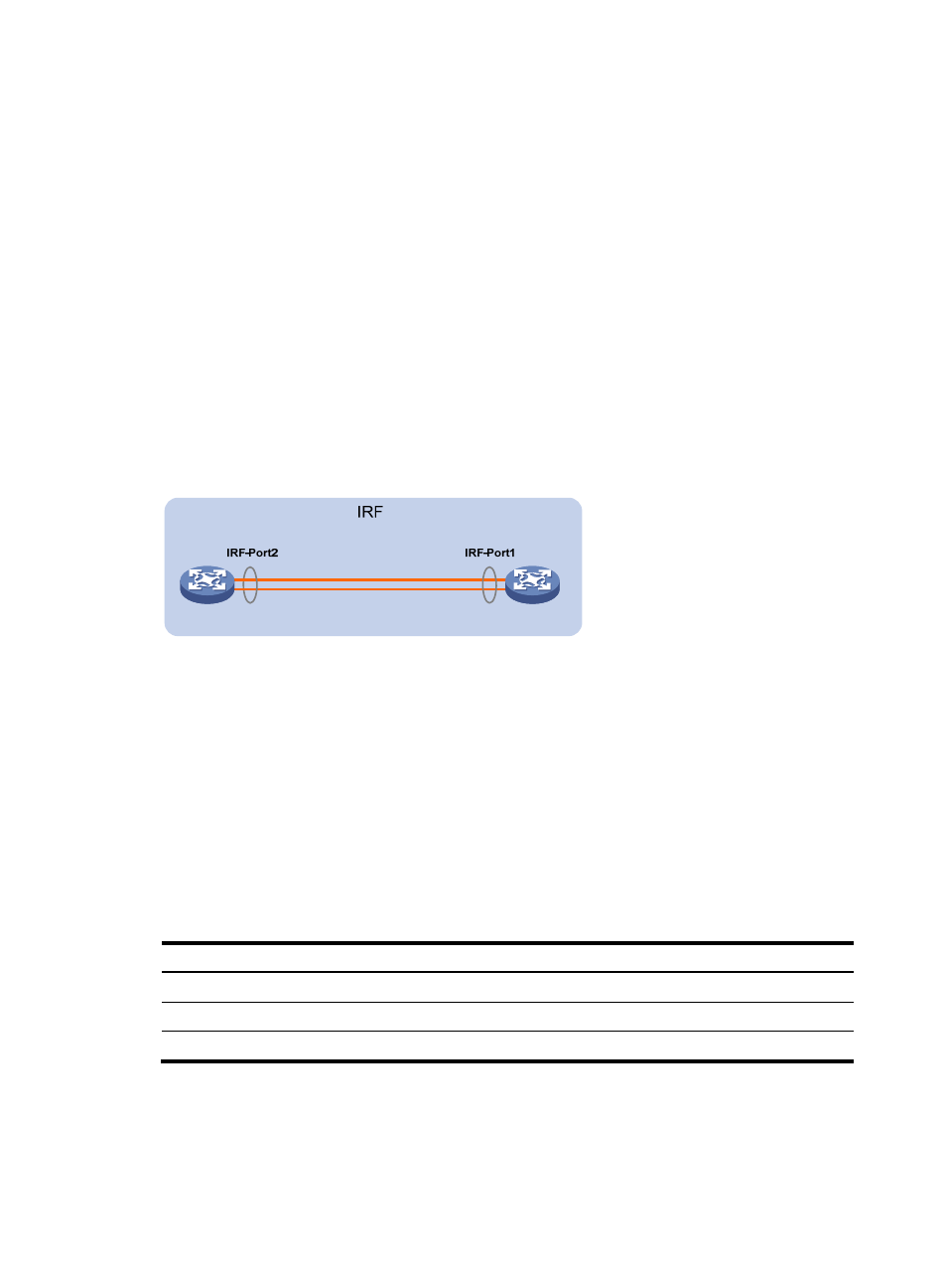
When connecting two neighboring IRF member switches, you must connect the physical ports of IRF-port
1 on one switch to the physical ports of IRF-port 2 on the other switch.
A two-member IRF fabric must use the daisy chain topology.
Figure 56 Daisy chain topology
Identifying physical IRF ports on the member switches
Identify the physical IRF ports on the member switches according to your topology and connection
scheme.
On H3C S9800 switches, only 10-GE/40-GE/100-GE ports can be used for IRF connection.
The H3C S9800 switches support multi-card link aggregation for IRF ports. You can bind up to eight
physical ports to one IRF port.
Installing IRF member switches
Step Reference
1.
Prepare the installation site.
See "Preparing for installation."
2.
Mount the IRF member switches to racks.
3.
Install modules on IRF member switches.