Configuration, Craft interface, Terminal setup – Verilink QUAD T1 (880-503345-001) Product Manual User Manual
Page 27: Craft interface -1, Terminal setup -1, Chapter
Verilink QUAD T1 User Manual
3-1
Chapter
3
Configuration
This chapter describes the process of configuring the QUAD T1
module through the SCM Craft interface.
Craft Interface
Verilink refers to the ASCII terminal interface of the AS3000
products as a Craft interface. Application modules can be
configured, circuits built, diagnostics performed and performance
monitored using the Craft interface.
Terminal Setup
Set your terminal parameters to:
•
Data rate: 19.2 kbit/s
•
Word size: 8 bits
•
Parity: None
•
Stop bits: One
•
Flow control: None
The Verilink Craft interface does not assert any control leads.
Verilink provides two types of Craft cable. Both versions of the
Craft cable have an RJ-11 modular connector at one end. The
original cable has a female DB-25 connector at the other end and a
more recent version has a DB-9 female connector. Connect the RJ-
11 modular connector to the port labeled
LOCAL
on the front of the
SCM module.
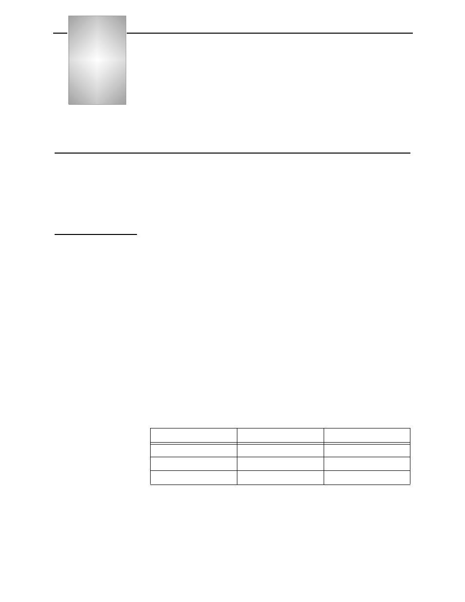
The original Craft cable pinout is shown in
.
Table 3-1 DB-25 Craft Cable P/N 458-501788-008
Your computer may have a DB-9 connector for the COM port. If it
does, use the DB-9 type Craft cable shown in
or use a
second cable or adapter to complete the connection. To adapt a DB-
25 Craft cable to a DB-9 COM port, use the same type of PC serial
cable as would be used to connect to an external modem.
DB-25 female
RJ-11 modular
Usage
pin 2
pin 3
Transmit Data
pin 3
pin 4
Receive Data
pin 7
pin 5
Signal Ground