Supervisory port connection, Supervisory port connection – Verilink PRISM 3060-10 (34-00252.4) Product Manual User Manual
Page 20
12
I
NSTALLATION
The NMS address, NMS bit rate, and boot configuration mode are set by the front
control panel as described in page 33. The physical connection of the NMS port is
a 6 -pin modular connector with the pinout shown in Table 2-5. This is a serial
RS232-level port configured for 8 bits, no parity, and 1 stop bit.
Supervisory
Port
Connection
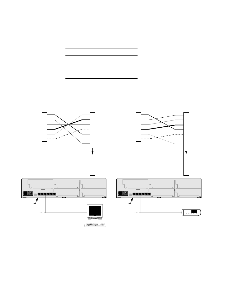
The rear panel SUPV port serves several functions. The terminal interface program
may be accessed through this port. A modem may be connected to this port for
remote access or use of the call-on-alarm feature (see Figure 2-4).
The supervisory port is an independent serial interface into the unit and plugging
into it does not interrupt the NMS port traffic. The supervisory port bit rate must
be set by the front control panel (see Supv Bit Rate on page 33).
Table 2-5 NMS In and Out Pinouts
Pin
NMS BUS IN
NMS BUS OUT
1, 6
not used
not used
2, 5
Signal Ground
Signal Ground
3
Data Out
Data Out
4
Data In
Not Used
O
I
O
I
PRISM 3060 Rear Panel
NMS IN
may also
be used
RS-232 to Terminal
(PN 9-1001-028-1)
NMS IN
may also
be used
RS-232 to Modem
(PN 9-1001-027-1)
Modem
Terminal
Supervisory Port
Control Out
Data Out
Data In
Signal Gnd
Control In
Terminal (DTE)
TXD
RXD
RTS
CTS
Signal
GND
DB-25
1
2
3
4
5
6
1
2
3
4
5
6
7
20
21
22
23
PRISM 3060 Rear Panel
Supervisory Port
Control Out
Data Out
Data In
Signal Gnd
Control In
Modem (DCE)
TXD
RXD
RTS
CTS
Signal
GND
DB-25
1
2
3
4
5
6
1
2
3
4
5
6
7
20
21
22
23
Figure 2-4 NMS Connections to the 3060-10 through a Modem and a Terminal