Midi in/thru/out connector pinout, Lynx (remote controller) connector pinout, Editor connector pinout – Teac MMR-16 v4.0 User Manual
Page 132
TASCAM MMP-16 Owner’s Manual • Appendix D • Cable Information
134
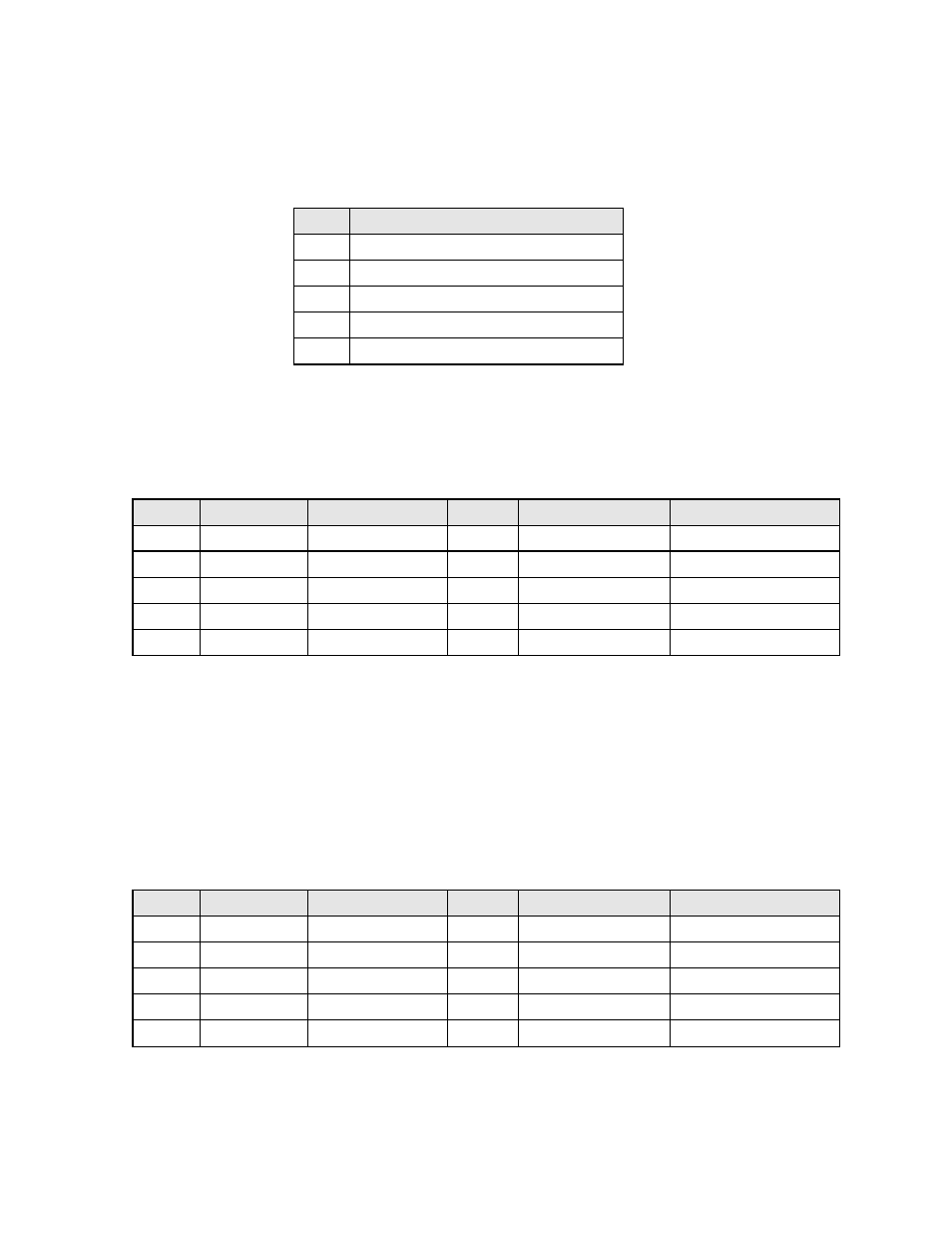
MIDI IN/THRU/OUT Connector pinout
PIN #
Signal Description (IN, OUT, & THRU)
1
n/c
2
n/c
3
n/c
4
Signal +
5
Signal -
NOTES:
1.
DIN-5 connector - shield tied to case.
2.
Signals are MIDI specification compliant.
LYNX (Remote Controller) Connector pinout
PIN #
MSTR Signal
SLAVE Signal
Pin #
MSTR Signal
SLAVE Signal
1
Frame ground
Frame ground
6
Frame ground
Frame ground
2
Receive -
Transmit -
7
Receive +
Transmit +
3
Transmit +
Receive +
8
Transmit -
Receive -
4
Frame ground
Frame ground
9
Frame ground
Frame ground
5
Frame clock
Frame clock
NOTES:
1. 9-pin D-subminiature female connector (DB-9).
2. Signals are RS422 Compatible Frame clock is open collector driver.
3. The two connectors allow parallel connection of the Lynx Bus. Each pin is
paralleled internally between the two connectors. The signal description
indicates master / slave signals.
EDITOR Connector pinout
PIN #
MSTR Signal
SLAVE Signal
Pin #
MSTR Signal
SLAVE Signal
1
Frame ground
Frame ground
6
Frame ground
Frame ground
2
Receive -
Transmit -
7
Receive +
Transmit +
3
Transmit +
Receive +
8
Transmit -
Receive -
4
Frame ground
Frame ground
9
Frame ground
Frame ground
5
Spare Fr Ck
Spare Fr Ck
NOTES:
1. 9-pin D-subminiature female connector (DB-9).
2. Signals are RS422 Compatible. Frame Clock spare should not be used.