Sloan 601 Prison Flushometer User Manual
Page 6
6
C
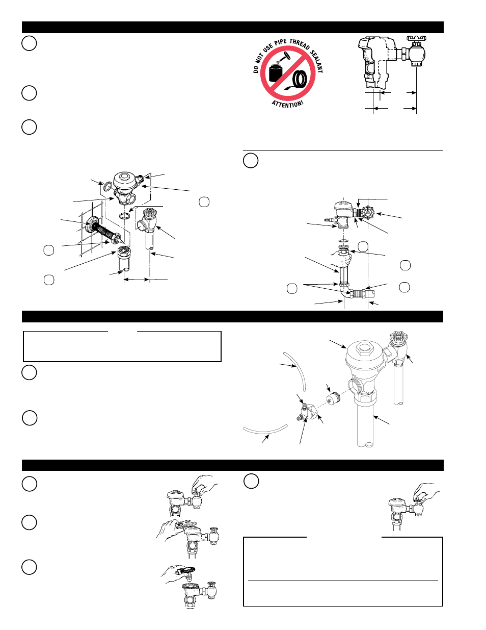
STANDARD PUSH BUTTON ONLY:
Align flushometer body. Using a wrench, securely tighten couplings
in the order given:
(1) tailpiece coupling, (2) actuator coupling, (3)
vacuum breaker coupling,
(4) slip joint couplings, and (5) spud
coupling.
B
Align flushometer directly above the vacuum breaker flush connection
by sliding the flushometer Body IN or OUT as needed. Tighten vacuum
breaker coupling by hand.
A
Insert adjustable tailpiece into control stop. (For standard push button,
also mount flushometer to actuator assembly.) Lubricate tailpiece
o-ring with water. Hand tighten tailpiece coupling. (For standard push
button, also hand tighten actuator assembly coupling).
4-1/4”
(108 mm)
5-1/4”
(133 mm)
MIN.
MAX.
B
Slide platic tubing into its corresponding valve actuator fitting. Pull
tubing to make sure connection is secure. (Tubing can be removed
by pressing on blue connection button to release.)
A
Cut off excess plastic tubing with plastic tube cutter (PTC) so that
there will be about 3” to 4” (76-102 mm) of slack when push button
actuator is installed. If the “L” and “O” markings on the tube will be
cut off, remark the tubing appropriately to not lose identification.
HY-83-A
ACTUATOR
CARTRIDGE
ASSEMBLY
VACUUM
BREAKER TUBE
HOUSING
COUPLING
NUT
VALVE ACTUATOR
HOUSING
FLUSHOMETER
VALVE BODY
PLASTIC TUBING
BAK-CHEK
®
CONTROL STOP
QUICK CONNECT
FITTINGS (2)
Shut off control stop by turning handle
CLOCKWISE. Then remove flushometer
cover.
A
OBSERVE “L” AND “O” MARKINGS ON TUBING. TUBING MUST
BE CONNECTED TO CORRESPONDING “L”AND “O” MARKINGS ON
PUSH BUTTON ACTUATOR.
NOTE
Lift out the inside parts assembly as a
complete unit. Reinstall flushometer cover
and tighten with wrench. Open control
stop. Turn on water supply to flush line of
any debris or sediment.
B
D
HYDRAULIC PUSH BUTTON ONLY:
Align flushometer body. Using a wrench, securely tighten couplings in
the order given:
(1) tailpiece coupling, (2) vacuum breaker coupling,
(3) slip joint couplings, and (4) pipe coupling.
A-31 GASKET
ADJUSTABLE
TAILPIECE
TAILPIECE
COUPLING
G-44
GASKET
CONTROL
STOP
C/L SUPPLY
C/L VACUUM
BREAKER TUBE
VACUUM BREAKER
COUPLING
ACTUATOR ASSEMBLY
COUPLING
ACTUATOR
MOUNTING NUT
FLUSHOMETER
BODY
4-3/4” (121 mm)
0-RING
TAILPIECE
COUPLING
VACUUM BREAKER
COUPLING
PIPE COUPLING
C/L SUPPLY
C/L FIXTURE
SLIP JOINT
COUPLINGS
VACUUM BREAKER
FLUSH CONNECTION
FLUSHOMETER
BODY
CONTROL
STOP
ADJUSTABLE
TAILPIECE
Maximum adjustment of Sloan Adjustable Tailpiece is 1/2” (13 mm) IN
or OUT from the standard 4-3/4” (121 mm) (flushometer centerline to
Control Stop centerline). If roughing-in measurement exceeds 5-1/4”
(133 mm), consult factory for longer tailpiece.
C
Shut off control stop and remove flushometer
cover. Reinstall inside parts assembly and
flushometer cover. Tighten cover with
wrench. Open control stop and activate
flushometer valve.
Adjust control stop to meet flow rate required
for proper cleansing of fixture. Open control
stop COUNTERCLOCKWISE ONE FULL turn
from closed position. Activate flushometer.
Adjust control stop after each flush until the
rate of flow delivered properly cleanses the
fixture.
D
1
3
2
1
3
2
4
PLASTIC
TUBING
SLOAN PRISON MODEL FLUSHOMETERS ARE ENGINEERED FOR
QUIET OPERATION. EXCESSIVE WATER FLOW CREATES NOISE,
WHILE TOO LITTLE WATER FLOW MAY NOT SATISFY THE NEEDS
OF THE FIXTURE. PROPER ADjUSTMENT IS MADE WHEN THE PLUMBING
FIXTURE IS CLEANSED AFTER EACH FLUSH WITHOUT SPLASHING WATER
OUT FROM THE LIP AND A QUIET FLUSHING CYCLE IS ACHIEVED.
NEVER OPEN CONTROL STOP TO WHERE THE FLOW FROM THE VALVE
EXCEEDS THE FLOW CAPABILITY OF THE FIXTURE. IN THE EVENT OF A
VALVE FAILURE, THE FIXTURE MUST BE ABLE TO ACCOMMODATE A
CONTINUOUS FLOW FROM THE VALVE.
!!! IMPORTANT !!!
4 - INSTALL FLUSHOMETER
5 - INSTALL TUBING TO VALVE ACTUATOR (HYDRAULIC PUSH BUTTON APPLICATIONS ONLY)
6 - FLUSH OUT SUPPLY LINE AND ADjUST CONTROL STOP
- 603 Prison Flushometer 611 Prison Flushometer 681 Prison Flushometer 609 Prison Flushometer 613 Prison Flushometer 9603 Prison Flushometer 9609 Prison Flushometer 9613 Prison Flushometer 111 UPPERCUT Flushometer 113 UPPERCUT Flushometer 115 UPPERCUT Flushometer 116 UPPERCUT Flushometer 120 UPPERCUT Flushometer