Sloan 601 Prison Flushometer User Manual
Page 4
4
B
Screw threaded rod into back of push button actuator.
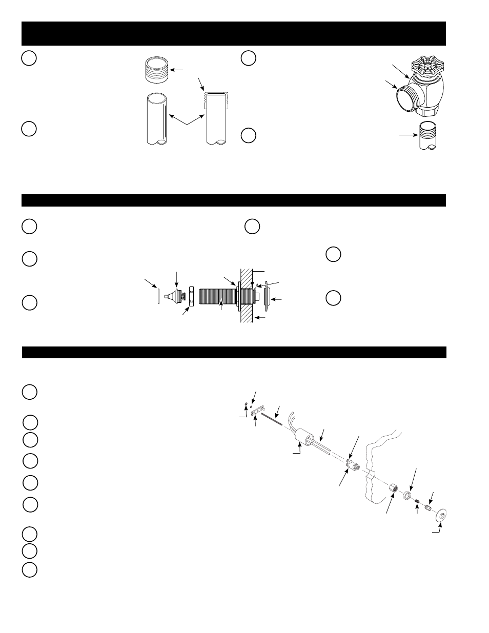
TO MOUNT ACTUATOR FROM FIXTURE SIDE:
Remove the bushing assembly, coupling nut and mounting nut from
the actuator shaft. Insert the actuator Shaft through the opening in
front of the wall.
A
TO MOUNT ACTUATOR FROM BEHIND THE WALL:
Remove the Flange and insert Actuator Shaft and Bushing
Assembly from the back of the wall through the Combination
Fixture or 1-1/2” (38 mm) wall opening.
A
B
Apply several drops of thread
sealant to threads of Actuator
Shaft at location shown.
C
Reinstall and tighten
the Flange. Tighten the
Mounting Nut against
the back of the wall.
B
Remove flange from actuator shaft.
Apply several drops of thread sealant
to threads of actuator shaft at location
shown. Reinstall and tighten the flange.
C
Reinstall Mounting Nut onto the
actuator shaft. Tighten securely until
it is against the back of the wall.
Reinstall the coupling nut, bushing
assembly and A-31 Gasket.
A-31 GASKET
BUSHING
ASSEMBLY
COUPLING NUT
ACTUATOR
SHAFT
MOUNTING
NUT
FLANGE
WALL (FIXTURE SIDE)
1-1/2” DIA. HOLE
THREAD SEALANT
(SEE STEP B)
If not already completed, bore a 1-1/2” (38 mm) diameter hole in wall
for the push button actuator. Refer to the Rough-in drawings on
Pages 2 and 3.
A
C
Thread actuator assembly nut onto threaded end of push button
actuator.
D
Slide spring over metal push button until it snaps into place.
Insert metal push button into button flange.
E
Place spacer ring over threads of button flange and thread button
flange assembly into actuator assembly nut.
F
From behind wall, run plastic tubing through optional spacer sleeve
(notched end of sleeve toward rear) and wall. Spacer sleeve only
required if wall thickness is LESS than 2” (51 mm).
H
Insert push button actuator assembly into the 1-1/2” wall hole.
I
From behind wall, slide spacer sleeve (if required) over threaded
rod and rest it against rear of wall. Slide retaining bar onto threaded
rod and into slots of sleeve (if required), or against wall if sleeve is
not required. Install lockwasher and nut onto threaded rod. Tighten
securely. Carefully cut excess threaded rod, making certain to not
damage plastic tubing.
MBFW (METAL BUTTON - FIXTURE WALL) VARIATION HY-100-A METAL PUSH BUTTON ACTUATOR
BUTTON FLANGE
METAL
PUSH
BUTTON
SPRING
SPACER
RING
ACTUATOR
ASSEMBLY
NUT
WALL
PUSH
BUTTON
ACTUATOR
QUICK
CONNECT
FITTINGS (2)
PLASTIC
TUBING
SPACER SLEEVE --
USE ONLY IF WALL
THICKNESS IS LESS
THAN 2” (51 mm)
THREADED
ROD
LOCKWASHER
RETAINING
BAR
NUT
G
Attach plastic tubing. See: steps to attach plastic tubing on page 5.
Note: Behind wall access required to install HY-100-A Metal Push Button Actuator.
2A - INSTALL PUSH BUTTON ACTUATOR – STANDARD PUSH BUTTON APPLICATION ONLY
2B - INSTALL PUSH BUTTON ACTUATOR – HYDRAULIC PUSH BUTTON APPLICATION ONLY
1 - INSTALL OPTIONAL SWEAT SOLDER ADAPTER (ONLY IF SUPPLY PIPE DOES NOT HAVE MALE THREAD) AND INSTALL
CONTROL STOP
C
Install the Sloan Bak-Chek
®
Control
Stop to the water supply line with
the outlet positioned as required.
Note: For standard and hydraulic
push button applications, concealed
valves can be installed with the
Control Stop on either the left or
right side of the valve.
A
For Sweat Solder
applications, slide
Threaded Adapter
onto water supply pipe
until end of pipe rests
against shoulder of
Adapter.
B
Sweat solder the
Adapter to pipe.
D
Install Push Button Actuator by
following Step 2A, 2B or 2C
depending on your application.
THREADED
ADAPTER
WATER
SUPPLY
PIPE
BAK-CHEK
®
CONTROL STOP
IRON PIPE NIPPLE
OR COPPER PIPE
WITH
SWEAT SOLDER
ADAPTER
OUTLET
- 603 Prison Flushometer 611 Prison Flushometer 681 Prison Flushometer 609 Prison Flushometer 613 Prison Flushometer 9603 Prison Flushometer 9609 Prison Flushometer 9613 Prison Flushometer 111 UPPERCUT Flushometer 113 UPPERCUT Flushometer 115 UPPERCUT Flushometer 116 UPPERCUT Flushometer 120 UPPERCUT Flushometer