Chapter 2: introduction, 1 overview, Introduction – Sensoray 826 User Manual
Page 7: Overview
Chapter 2: Introduction
2.1 Overview
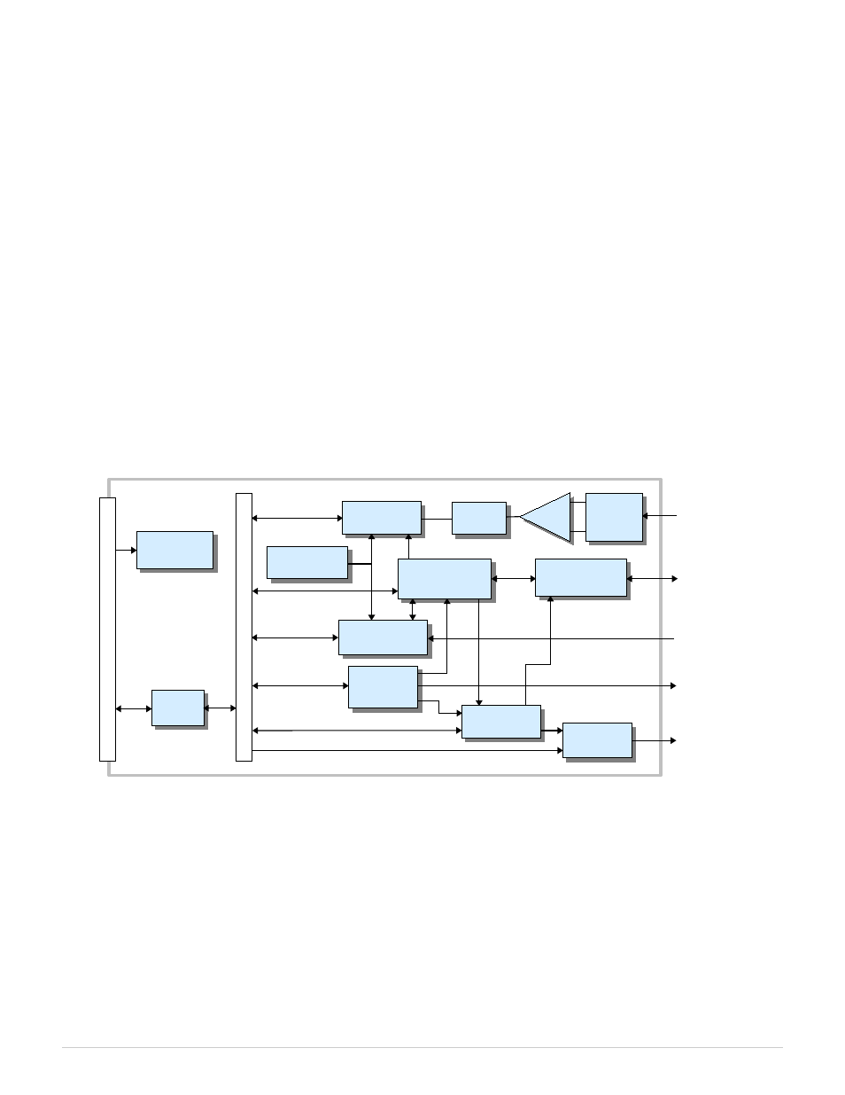
Model 826 is a PCI Express board that features an assortment of I/O interfaces commonly used in measurement and control
applications:
•
48 bidirectional digital I/O channels with edge detection and fail-safe output control.
•
Eight 16-bit analog outputs (±10V, ±5V, 0-10V, 0-5V) with fail-safe output control.
•
Sixteen 16-bit differential analog inputs (±10V, ±5V, ±2V, ±1V) with hardware and software triggering.
•
Six 32-bit counters. Clock inputs may be driven from external quadrature-encoded (e.g., incremental encoder) or
single-phase sources. Inputs accept differential RS-422 or standard TTL/CMOS single-ended signals. Auxiliary inputs
and outputs can be internally routed to digital I/O channels.
•
Multistage watchdog timer that can activate fail-safe outputs and generate service requests.
•
Fail-safe controller switches outputs to safe states upon watchdog timeout or external trigger.
•
Signal routing matrix allows software to interconnect interfaces without external wiring.
Figure 1: Model 826 block diagram
Sensoray provides a free, comprehensive API (application programming interface) to facilitate the rapid development of
polled, event-driven, or mixed-mode programs for Model 826. The API works in concert with the board's advanced
architecture to support complex, high performance applications.
Standard headers are provided for connecting on-board peripherals to external circuitry. The board's low-profile headers
allow it to fit comfortably into high-density systems, and an integral cable clamp keeps cables secure and organized.
On-board LEDs provide visual indications of the board's condition. The PWR indicator is lit when the on-board power
supplies are operating. Six LEDs are used to indicate counter clock activity as explained in Status LEDs.
826 Instruction Manual
2
Introduction
Signal
Routing Matrix
DC-to-DC
Converters
Counter
Channels
3-Stage
Watchdog
Fail-safe
Controller
DAC
Channels
Digital I/O
Interface
Analog
Mux
ADC
ADC
Controller
Timestamp
Generator
PCIe
Bridge
P
C
Ie
B
us
16 Analog In
Lo
ca
l B
us
8 Analog Out
6 Counter/Timer
Encoder
48 Digital I/O
Reset Out
PGA