2 quadrature decoder, 3 extin signal, 4 extout signal – Sensoray 826 User Manual
Page 33: Quadrature decoder, Extin signal, Extout signal
The ClkA, ClkB, and IX inputs employ differential RS-422 line receivers for buffering and noise immunity. All line
receivers have built-in termination resistors. The clock and IX inputs are compatible with differential RS-422 signal pairs as
well as single-ended TTL and 5V CMOS signals.
Each line receiver is followed by a noise filter that can be used to remove glitches. See S826_CounterFilterWrite for details.
7.1.2 Quadrature Decoder
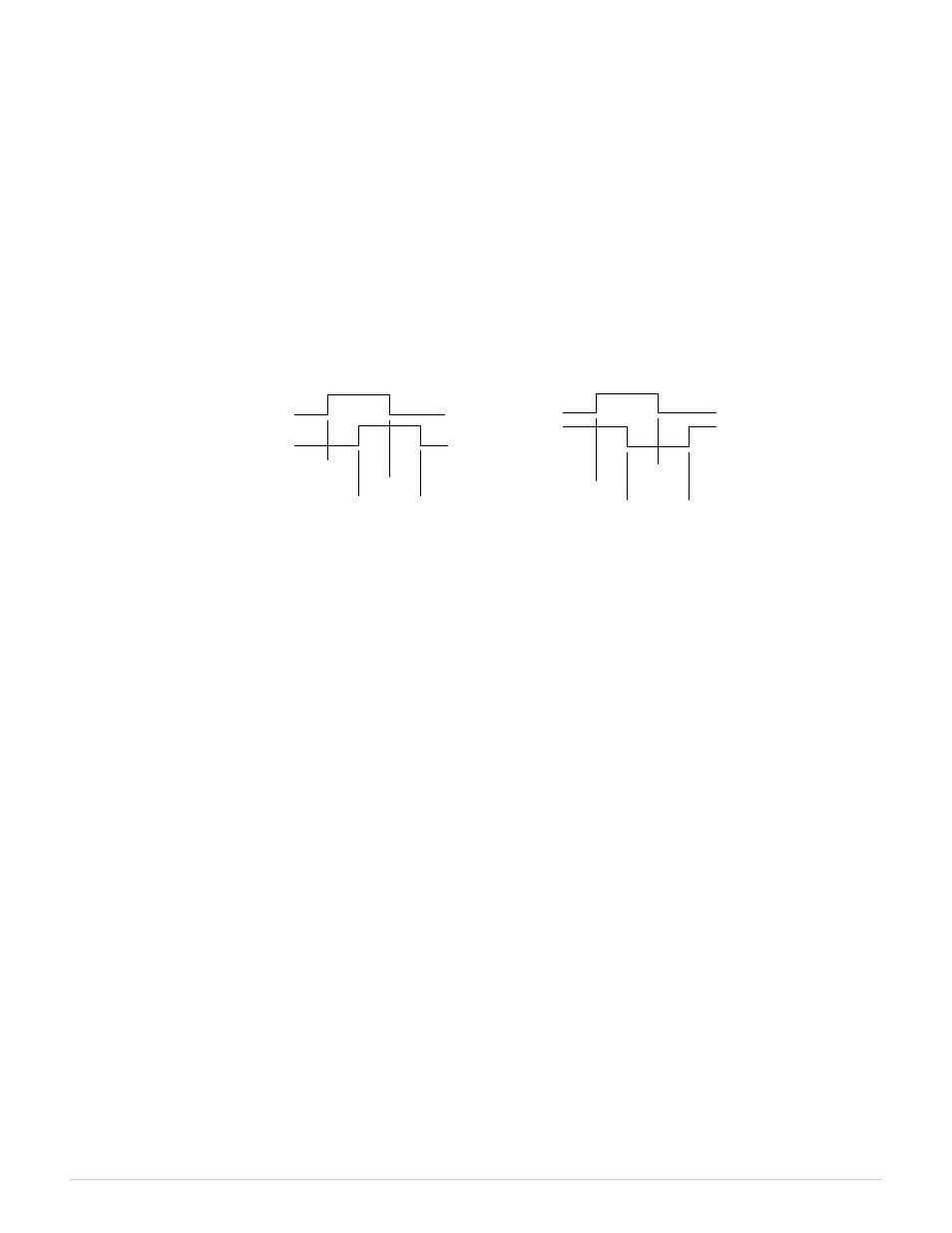
When connected to quadrature-encoded clock signals, the ClkA and ClkB signals are processed by a quadrature decoder
circuit to produce count direction, count enable, and quadrature error signals. Figure 6 shows the clock events that affect
counting for each of the possible clock multipliers.
Figure 6: Quadrature Decoding
Increment Counts
Decrement Counts
For example, with a x1 (“times 1”) multiplier, the counts will only change when ClkB is low; the core will count up on the
rising edge of ClkA and down on the falling edge of ClkA.
If the decoder detects an encoding error, it will generate a special error snapshot (see Snapshots below) and set an internal
error flag. This will happen when ClkA and ClkB transition within 20 ns of each other (which should never occur in normal
operation). This can be caused by various conditions, including signal noise on ClkA/ClkB or excessively high input clock
frequency. The error snapshot serves as a warning that the counter core may no longer contain an accurate counts value.
7.1.3 ExtIn Signal
Some applications may require an additional external input (ExtIn) signal. If needed, this signal can be routed from any
general-purpose digital I/O (DIO) channel, any virtual digital output channel, or the ExtOut signal of any counter channel
(see Section 7.3.12 for details). When ExtIn is routed from a DIO channel, the signal appearing on the DIO channel's
connector pin must conform to the timing constraints of the DIO subsystem as explained in “Pin Timing”.
The ExtIn signal can be configured to behave as either a count or preload permissive by programming the IM field in the
Mode register. See S826_CounterModeWrite for details.
7.1.4 ExtOut Signal
Some counter applications (e.g., pulse or PWM generator) may require a physical output from the counter. In such cases,
the counter's ExtOut signal may be routed to a general-purpose DIO channel (see Section 8.3.12 for details). When so
routed, the DIO channel will act as a dedicated counter output, while the DIO input and edge detection functions continue
to operate normally.
When routed to a DIO, the ExtOut signal timing is constrained by the DIO subsystem as explained in “Pin Timing”. In
particular, the ExtOut signal may be delayed up to 20 ns before it appears on the DIO connector pin. Note also that short,
positive output pulses may require the addition of external, supplemental pull-up resistance on the DIO pin to attain
sufficiently fast rise time.
A channel's ExtOut signal will be asserted only when the channel is running. When the channel is halted, ExtOut is held at
the inactive state, as defined by its configured polarity.
826 Instruction Manual
28
Counters
ClkA
ClkB
x1
x2
x2
x4
x4
x4
x4
ClkA
ClkB
x4
x2
x1
x2
x4
x4
x4